A simple three-dimensional positioning installation and load-bearing device and its application method

A three-dimensional positioning and simple technology, which is applied in hoisting devices, portable lifting devices, transportation and packaging, etc., can solve problems such as low precision, complicated installation work, hidden safety hazards, etc., and achieve uniform force, uniform gravity, and convenient adjustment Effect

Active Publication Date: 2020-11-03
CHINA MCC17 GRP
View PDF6 Cites 0 Cited by
  • Summary
  • Abstract
  • Description
  • Claims
  • Application Information

AI Technical Summary

Problems solved by technology

[0005] The technical problem to be solved by this method is that there are certain safety hazards in the installation of the embedded parts using the existing technology, the construction cost is high, and there is a hidden danger that the structure of the embedded parts will collide during the installation process and the expected effect will not be achieved. Complicated installation work with low precision

Method used


Image

  • A simple three-dimensional positioning installation and load-bearing device and its application method
  • A simple three-dimensional positioning installation and load-bearing device and its application method
  • A simple three-dimensional positioning installation and load-bearing device and its application method

Examples


Embodiment 1

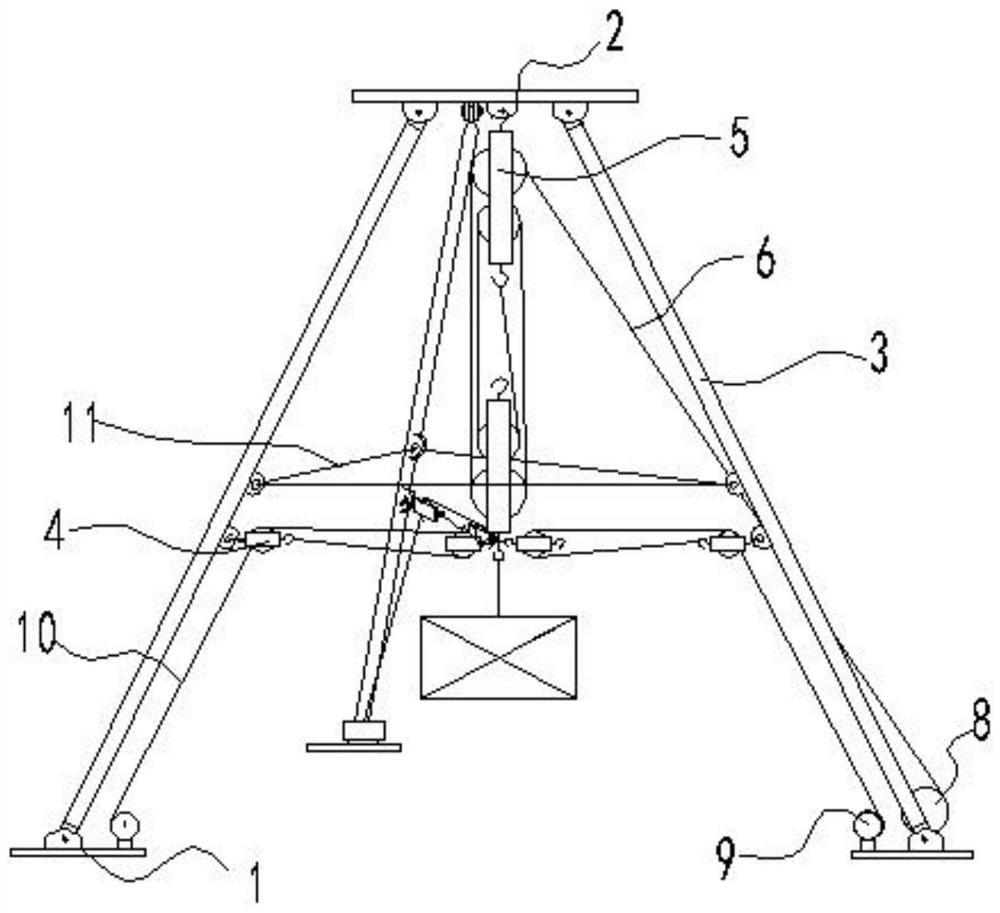
[0048] combine Figure 1 to Figure 10 As shown, a simple three-dimensional positioning installation and load-bearing device proposed by the present invention includes a load-bearing part, a lifting part and an adjusting part;

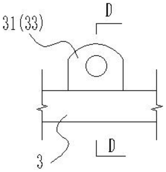
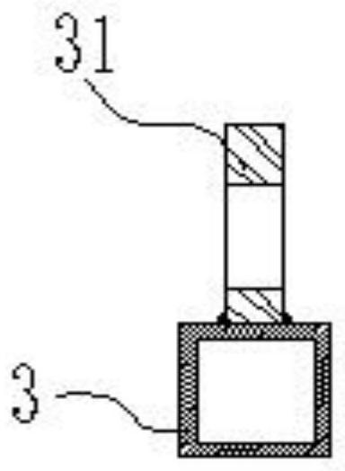
[0049] The load-bearing part includes a backing plate 1, a load-bearing plate 2 and a load-bearing rod 3.

[0050] The side of the backing plate 1 close to the load-bearing plate 2 is respectively welded and connected with the second connection block 7 with a thickness of 12mm and the first hoist 9 with a thickness of 12mm by bolts.

[0051] The side of the load-bearing plate 2 close to the backing plate 1 is welded and connected with a first load-bearing block 21 with a thickness of 12 mm and a first connection block 22 with a thickness of 12 mm, and the first load-bearing block 21 is located at the center of the load-bearing plate 2 , can make the bearing plate 3 evenly stressed. The first connecting block 22 is evenly arranged in three groups in th...

Embodiment 2

[0059] The invention also discloses a method for using a simple three-dimensional positioning installation and load-bearing device, which includes the following steps:

[0060] Step 1. Fix the side of all load-bearing rods 3 connected to the limit block 31 towards the inside of the overall device;

[0061] Step 2, all the third connection blocks 32 at the end away from the backing plate 1 are connected to the first connection block 21 with 12mm bolts;

[0062] Step 3, all the third connecting blocks 32 far away from the end of the bearing plate 2 are connected to the second connecting block 7 with 12mm bolts;

[0063] Step 4: The end of the first pulley group 5 away from the backing plate 1 is hooked to the first load-bearing block 21, and the end of all the second pulley groups 4 close to the load-bearing rod 3 is hooked to the second load-bearing block 33, and the second pulley group 4 is far away from the second load-bearing block. One end of the block 33 is hooked with th...


PUM


Abstract

The invention discloses a simple three-dimensional positioning installing and load-bearing device and a use method, and belongs to the technical field of positioning installing and hoisting of a steelstructural built-in fitting. The simple three-dimensional positioning installing and load-bearing device specifically comprises a load-bearing plate, cushion plates, a first pulley set, a second pulley set, a first winding machine, a second winding machine and load-bearing rods; two ends of the load-bearing rods are rotatably connected with the load-bearing plate and the cushion plates correspondingly, and hoisting of the built-in fitting of different specifications can be realized by adjusting the distance between the cushion plates. Connecting pieces are combined to perform limiting to prevent the load-bearing rods from being subjected to force and overturning outward. The first winding machine and the second winding machine are adjusted to adjust the second pulley set and the first pulley set, and positioning of the steel structural built-in fitting in the vertical direction and the horizontal direction is indirectly controller. The pulley sets are used to greatly reduce the construction labor, the construction cost is reduced, and the efficiency and the construction precision are improved.

Description

technical field [0001] The invention belongs to the field of embedded parts construction, and in particular relates to a simple three-dimensional positioning installation and load-bearing device and a construction method. Background technique [0002] In steel structure buildings such as gymnasiums, it is necessary to install large steel structure embedded parts to achieve special functional requirements and architectural shapes. In this kind of stadium steel structure project, there are often many large embedded parts that need to be constructed, while traditional embedded parts are generally heavy and bulky, which is inconvenient to move manually, resulting in construction difficulties. [0003] Today's traditional large embedded parts are usually hoisted by large cranes, resulting in high construction costs and not conducive to long-term hoisting. When the crane lifts the embedded parts, the positioning accuracy is too low, and the embedded parts will inevitably collide ...

Claims


Application Information

Patent Timeline
Patent Type & Authority Patents(China)
IPC IPC(8): B66D3/08B66C13/04
CPCB66C13/04B66D3/08B66D2700/028
Inventor 徐枫
Owner CHINA MCC17 GRP
Why Eureka
Try Eureka