
Inspection robot

A technology of inspection robot and walking mechanism, which is applied in the field of inspection robot, can solve the problems of high cost and large amount of equipment investment, and achieve the effect of balanced gravity, compact structure and reduced wear

Pending Publication Date: 2020-01-31
四川智鼎盛邦智能科技有限公司
View PDF0 Cites 0 Cited by
  • Summary
  • Abstract
  • Description
  • Claims
  • Application Information

AI Technical Summary

Problems solved by technology

[0003] Aiming at the deficiencies in the prior art, the present invention provides a patrol robot, which solves the problem of large investment and high cost caused by installing monitoring equipment at multiple points and fixed points in the traditional monitoring method

Method used


Image

  • Inspection robot
  • Inspection robot
  • Inspection robot

Examples


Embodiment 1

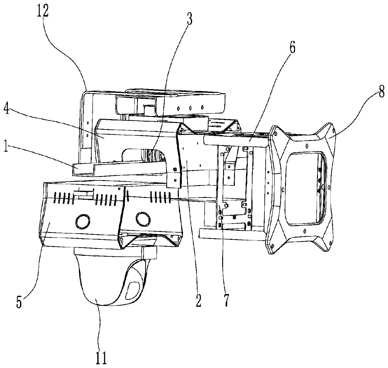
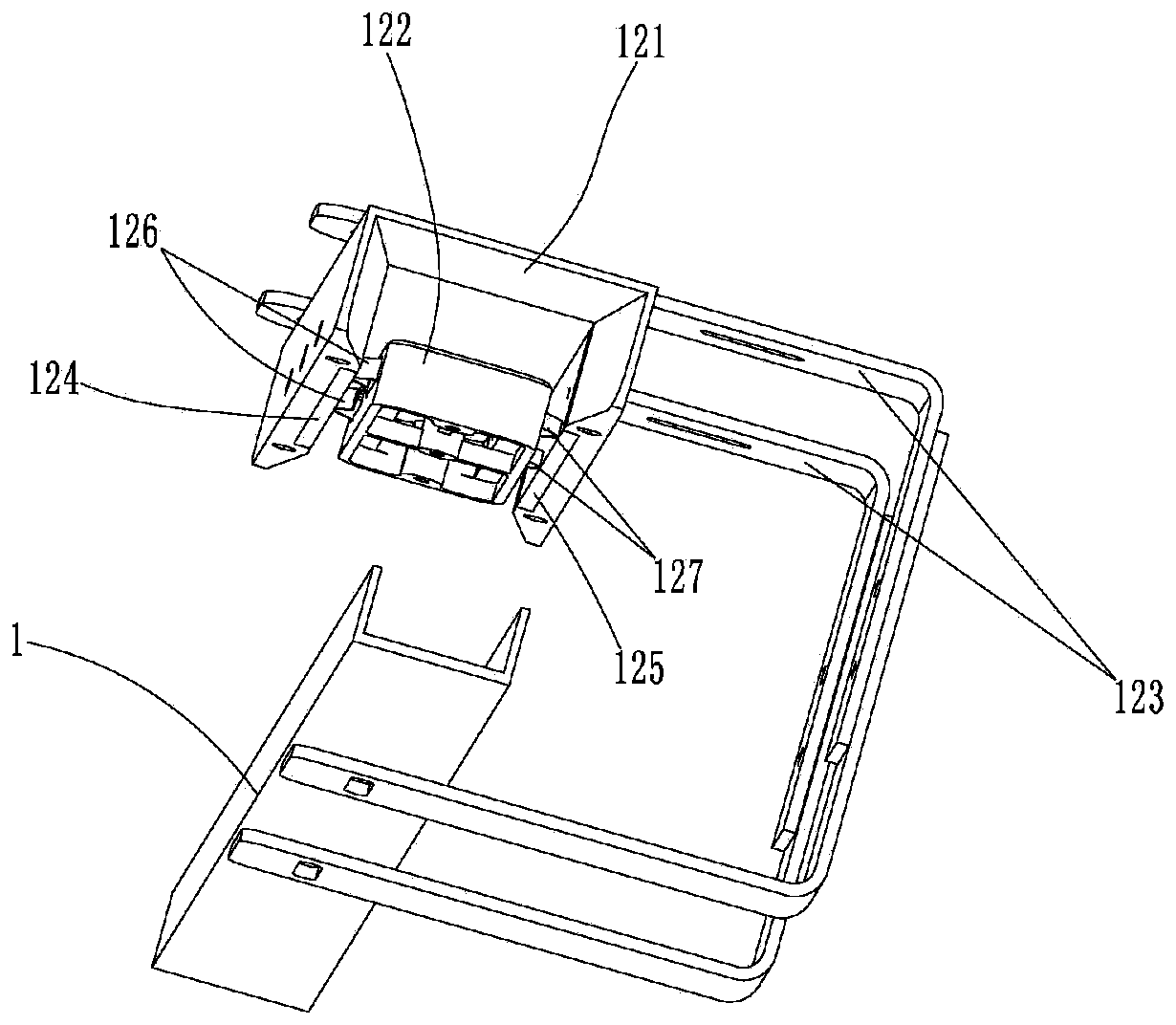
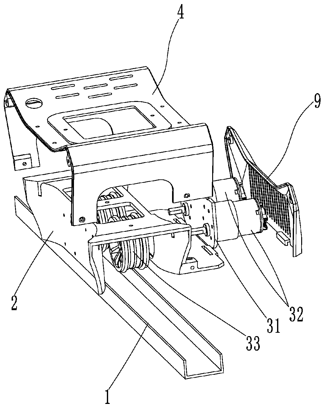
[0027] Such as Figure 1 to Figure 6 As shown, the present invention provides a kind of patrolling robot, comprises the annular rail 1 that cross section is groove shape, and described annular rail 1 is erected with protective shell 2, and described protective shell 2 is installed on the circular rail 1 moving The traveling mechanism 3, the traveling mechanism 3 comprises a motor connection plate 31 detachably installed on the inner side plate of the protective shell 2, two drive motors 32 are installed at intervals on the motor connection plate 31, and the rotation shafts of the two drive motors 32 extend Into the protective shell 2 and installed with a roller 33, the roller 33 is placed in the ring track 1 to roll, when the two drive motors 32 run, the drive roller 33 rolls in the ring track 1, thereby driving the whole machine on the ring track 1 move up. An upper casing 4 positioned above the casing 2 and a lower casing 5 positioned below the circular track 1 are installe...

Embodiment 2

[0036] Such as Figure 7 ~ Figure 8 As shown, in order to further improve the charging contact mode of the charging position, on the basis of Embodiment 1, the positive electrode sheet 126 is replaced by the positive electrode contact column 13, and the negative electrode sheet 127 is replaced by the negative electrode contact column 14, so The power receiving seat 122 is replaced with a contact column mounting seat 15, and the positive electrode contact column 13 and the negative electrode contact column 14 are slidably installed on the contact column mounting seat 15 through a spring, and the contact column mounting seat 15 The limited cover plate 16 is installed inside; when in use, both the positive electrode contact column 13 and the negative electrode contact column 14 are connected to the rechargeable lithium battery through wires, and when the whole moves to the position of the charging base 121, the positive electrode contact The column 13 is in elastic contact with t...


PUM


Abstract

The invention provides an inspection robot. The robot comprises an annular rail with a groove-shaped cross section, a protective shell is erected on the annular rail, and a walking mechanism moving onthe annular rail is arranged on the protective shell; an upper covering shell located above the protective shell and a lower covering shell located below the annular rail are arranged on the protective shell, a steel frame is arranged between the upper covering shell and the lower covering shell, and a mounting support for being connected with the protective shell is arranged on the steel frame;a side covering plate used for covering the steel frame is arranged between the upper covering shell and the lower covering shell, an upper covering plate used for covering the walking mechanism is arranged between the upper covering shell and the protective shell, and a lower covering plate is arranged on the lower covering shell; the bottom end of the lower covering shell is detachably providedwith an collecting device; the mounting support is provided with a circuit control plate and a charging lithium battery located in the lower covering shell, and the top end of the upper covering shellis provided with a router; and the robot further comprises a charging device used for charging the charging lithium battery. According to the robot, the current situations that according to a traditional monitoring method, monitoring devices are arranged at multiple points and fixed points, so that the equipment investment is large in quantity and high in cost are improved.

Description

technical field [0001] The invention relates to the technical field of monitoring equipment, in particular to an inspection robot. Background technique [0002] The monitoring system is a system that collects various signals in real time in an unattended place to ensure the safety of the monitored area. The most important component equipment in the monitoring system is monitoring equipment; in traditional monitoring methods, it is multi-point 1. To install monitoring equipment at a fixed point, it is necessary to install multiple monitoring equipment in the monitoring area for monitoring at multiple locations and angles, and the investment in equipment is large and the cost is high. Contents of the invention [0003] Aiming at the deficiencies in the prior art, the present invention provides a patrol robot, which solves the problem of large investment and high cost caused by installing monitoring equipment at multiple points and fixed points in the traditional monitoring m...

Claims


Application Information

Patent Timeline
Patent Type & Authority Applications(China)
IPC IPC(8): F16M11/42F16M11/02H02J7/00
CPCF16M11/02F16M11/425H02J7/0042
Inventor 王松张碧渊苏朝辉杨帆
Owner 四川智鼎盛邦智能科技有限公司
Learn More