Electronic component laser welding device and method

An electronic component, laser welding technology, applied in laser welding equipment, welding equipment, metal processing equipment and other directions, can solve the problems of damage to electronic components, surface damage of electronic components, etc., to achieve a small spot, reduce damage, and better welding quality. Effect

Inactive Publication Date: 2019-08-02
DONGGUAN BETTER ELECTRONICS TECH
View PDF9 Cites 5 Cited by
  • Summary
  • Abstract
  • Description
  • Claims
  • Application Information

AI Technical Summary

Problems solved by technology

However, touch welding has the risk of damaging the surface of electronic components due to direct impact; high-frequency welding has the risk of damaging electronic components due to the heating of the entire electronic component, and the heat-affected area

Method used


Image

  • Electronic component laser welding device and method
  • Electronic component laser welding device and method
  • Electronic component laser welding device and method

Examples


Embodiment 1

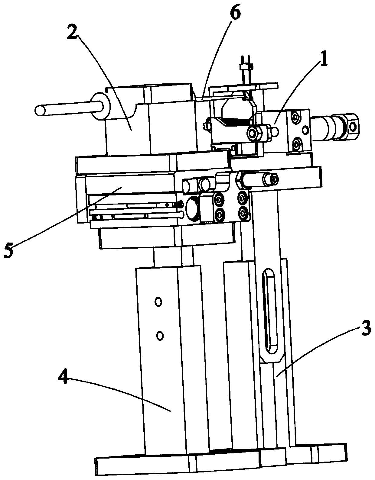
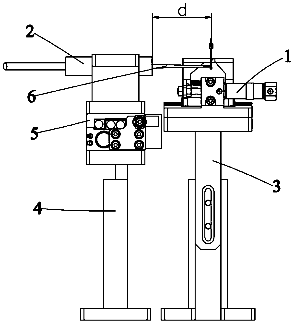
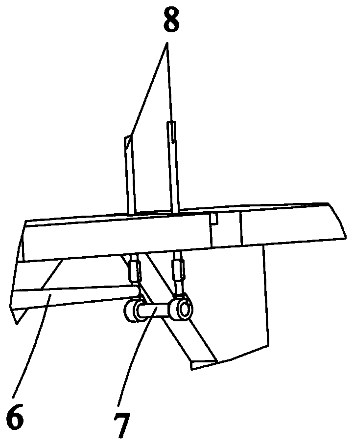
[0026] like Figure 1~3 As shown, a laser welding device for electronic components includes an electronic component fixing mechanism 1, a laser fiber optic lens 2, a first fixing bracket 3 and a second fixing bracket 4, and the electronic component fixing mechanism 1 is used to fix the main body 7 and the The lead wire 8, the electronic component fixing mechanism 1 is fixed on the first fixing bracket 3, the laser fiber lens 2 is installed on the second fixing bracket 4, and the laser beam 6 emitted by the laser fiber lens 2 is aligned with the connection between the main body 7 and the lead wire 8 place.

[0027] Further, the distance between the laser fiber lens 2 and the electronic component fixing mechanism 1 is d, the focal length of the laser fiber lens 2 is f, and d=f±5mm. The focal length f of the laser fiber lens 2 is 30mm.

[0028] Further, the present invention also includes a moving mechanism 5 , the moving mechanism 5 is arranged on the second fixed bracket 4 , ...

Embodiment 2

[0031] The difference from Embodiment 1 is that the focal length f of the laser fiber optic lens 2 is 50 mm.

[0032] The rest are the same as in Embodiment 1, and will not be repeated here.

Embodiment 3

[0034] The difference from Embodiment 1 is that the focal length f of the laser fiber optic lens 2 is 100 mm.

[0035] The rest are the same as in Embodiment 1, and will not be repeated here.


PUM

PropertyMeasurementUnit
lengthaaaaaaaaaa

Abstract

The invention belongs to the technical field of fuse wire production and particularly relates to an electronic component laser welding device. The electronic component laser welding device comprises an electronic component fixing mechanism, a laser fiber lens, a first fixed support and a second fixed support. The electronic component fixing mechanism is used for fixing a main body part and leadingwires of an electronic component; The electronic component fixing mechanism is fixed to the first fixed support. The laser fiber lens is mounted on the second fixed support. A laser beam emitted fromthe laser fiber lens is aligned with the junction between the main body part and the leading wires. Compared with the prior art, the electronic component laser welding device realizes accurate welding, reduces damage to the electronic component and improves the welding quality. In addition, the invention further provides an electronic component laser welding method. Through the electronic component laser welding device and method, operation is easy and convenient, and welding accuracy and welding quality are high.

Description

technical field [0001] The invention belongs to the technical field of electronic component production, and in particular relates to a laser welding device and method for electronic components. Background technique [0002] An electronic component is a basic element in an electronic circuit, usually individually packaged, and has two or more leads or metal contacts. Electronic components may be individual packages such as resistors, capacitors, inductors, transistors, diodes, fuses, etc. The electronic components listed above are all composed of a main body and lead wires connected to both ends of the main body. In the prior art, the main body and the leads are usually connected together by butt welding or high frequency welding. However, there is a risk of damage to the surface of electronic components due to direct impact in bump welding; high-frequency welding heats the entire electronic component, and the heat-affected area has a great risk of damaging electronic compo...

Claims


Application Information

Patent Timeline
Patent Type & Authority Applications(China)
IPC IPC(8): B23K26/21B23K26/70B23K26/08
CPCB23K26/0869B23K26/21B23K26/702
Inventor 龚卫彭秋云高连忠
Owner DONGGUAN BETTER ELECTRONICS TECH
Why Eureka
Try Eureka