
Numerical control machine tool with heat dissipation base

A technology of CNC machine tools and cooling bases, which is applied in the field of CNC machine tools, can solve the problems of affecting the transmission accuracy of CNC machine tools, not having a cooling base, and accelerating the wear of transmission parts, so as to improve the cooling effect, ensure the transmission accuracy, and prolong the service life.

Inactive Publication Date: 2019-07-30
罗瑞琪
View PDF11 Cites 0 Cited by
  • Summary
  • Abstract
  • Description
  • Claims
  • Application Information

AI Technical Summary

Problems solved by technology

[0005] The object of the present invention is to provide a numerically controlled machine tool with a heat dissipation base to solve the problem of not having a heat dissipation base proposed in the above background technology, which accelerates the wear of the transmission parts, thus affecting the transmission accuracy of the numerically controlled machine tool

Method used


Image

  • Numerical control machine tool with heat dissipation base
  • Numerical control machine tool with heat dissipation base
  • Numerical control machine tool with heat dissipation base

Examples


Embodiment Construction

[0025] The following will clearly and completely describe the technical solutions in the embodiments of the present invention with reference to the accompanying drawings in the embodiments of the present invention. Obviously, the described embodiments are only some, not all, embodiments of the present invention. The specific embodiments described here are only used to explain the present invention, not to limit the present invention. Based on the embodiments of the present invention, all other embodiments obtained by persons of ordinary skill in the art without making creative efforts belong to the protection scope of the present invention.

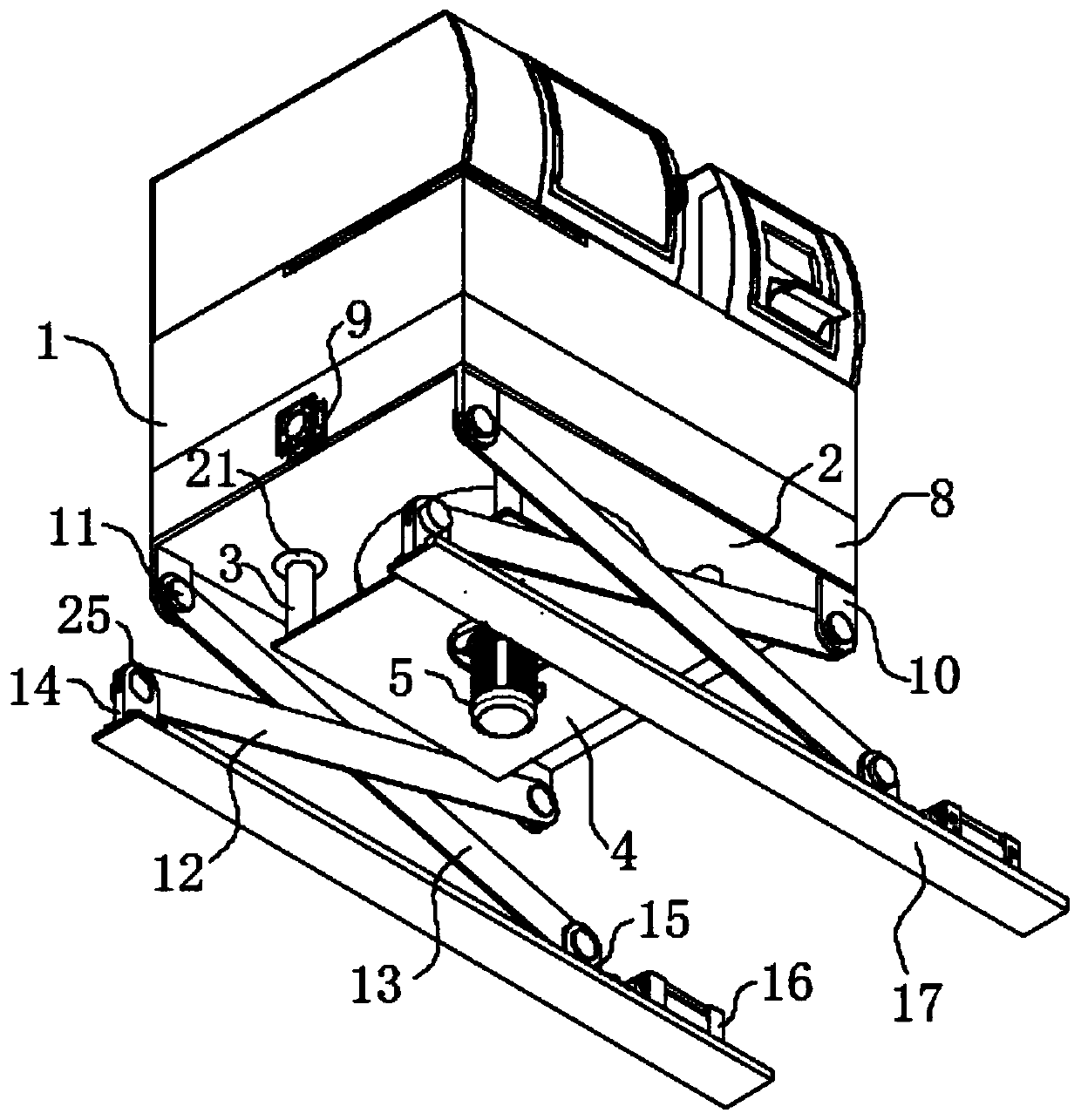
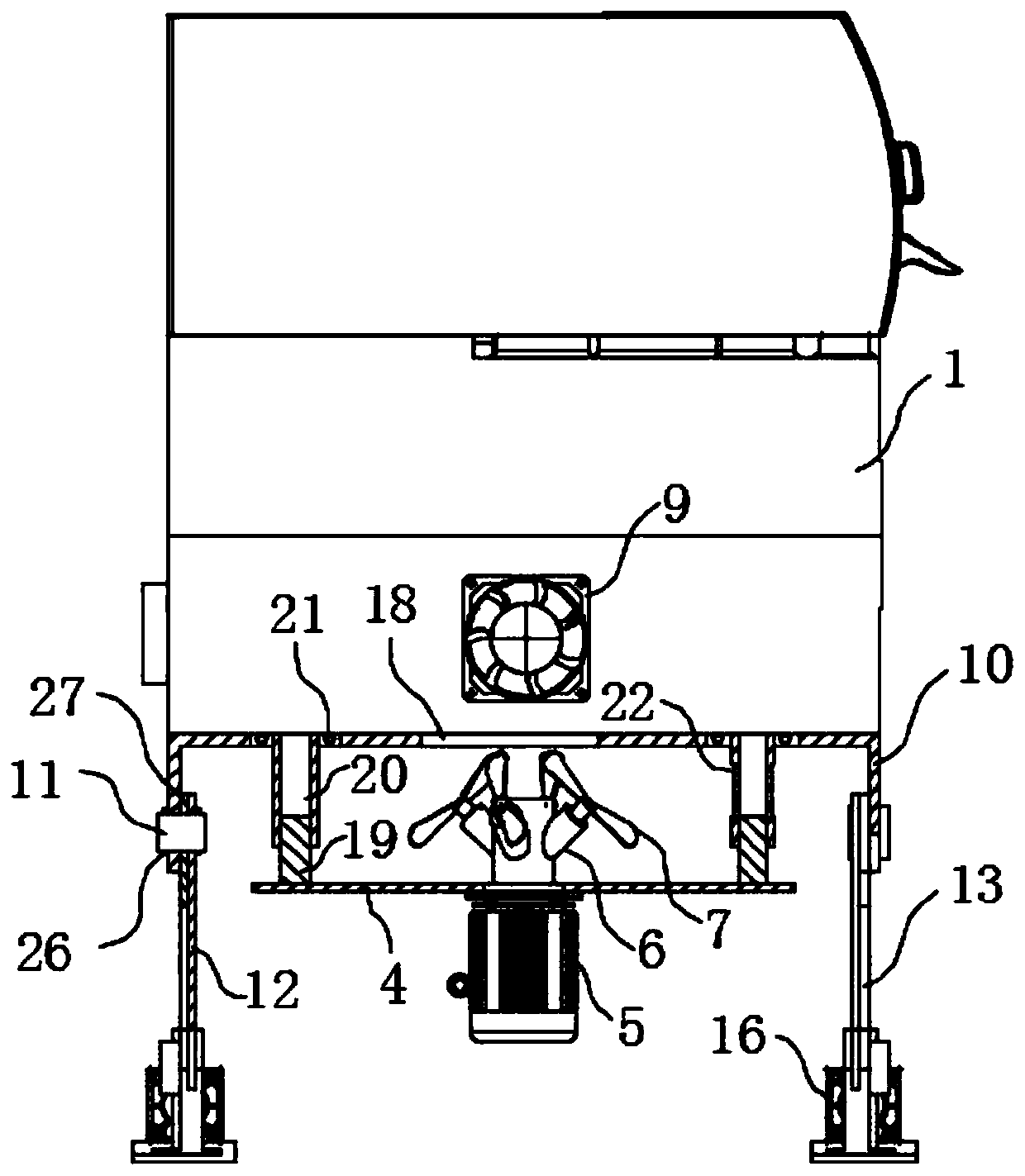
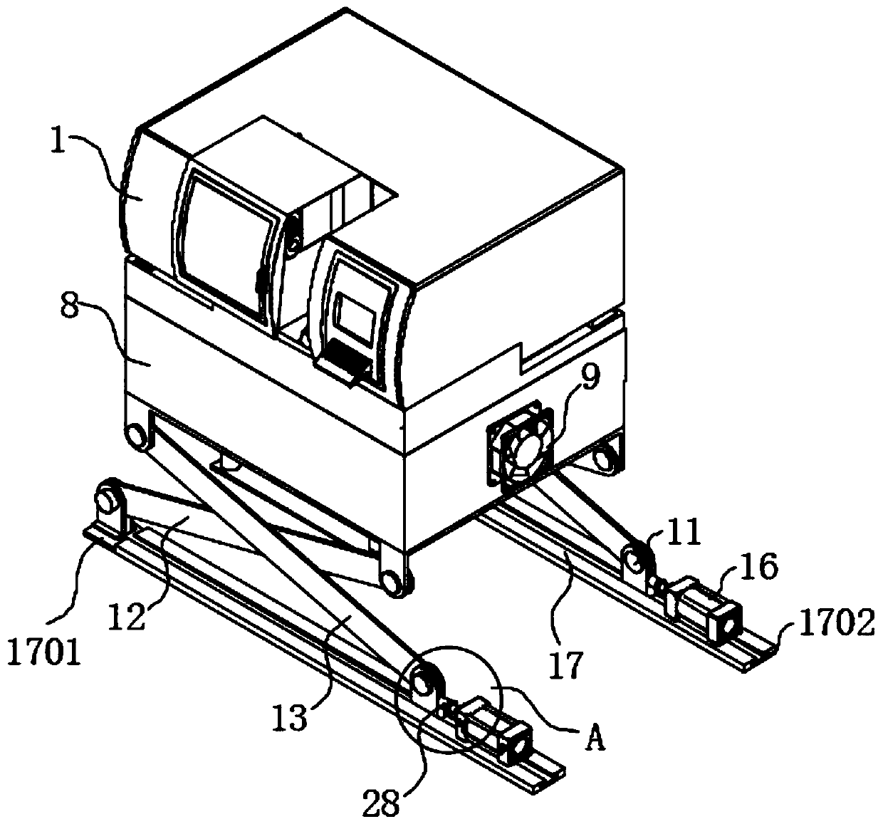
[0026] The present invention provides such Figure 1-5 A numerical control machine tool with a cooling base is shown, including a CNC machine tool body 1, a base 2 is fixedly installed at the bottom of the CNC machine tool body 1, and the base 2 is provided to support the entire CNC machine tool body 1; the bottom of the base 2 is ring-sh...


PUM


Abstract

The invention discloses a numerical control machine tool with a heat dissipation base. The numerical control machine tool comprises a numerical control machine tool body. The base is fixedly arrangedat the bottom of the numerical control machine tool body. Four groups of upright posts are annularly and equidistantly arranged at the bottom of the base. Connecting plates are fixedly arranged at thebottoms of the four groups of upright posts. A motor is fixedly arranged at the center of each connecting plate. Shaft sleeves are fixedly arranged at the tops of the motors. Four groups of heat dissipation devices are annularly and equidistantly distributed on the outer surface of each shaft sleeve. Lug plates are fixedly connected to four corners of the base. Two groups of fixing blocks and twogroups of guide blocks are correspondingly and movably connected with the ends, far away from the lug plates, of two groups of first connecting rods and two groups of second connecting rods. Electricpush rods are fixedly mounted on one sides of the two groups of guide blocks. Guide grooves are correspondingly and fixedly formed in the bottoms of the two groups of electric push rods. The two groups of fixing blocks are fixedly mounted at the ends, far away from the electric push rods, of the guide grooves. By the adoption of the numerical control machine tool, the service life of parts in thenumerical control machine tool is prolonged, and the transmission precision of the numerical control machine tool is ensured.

Description

technical field [0001] The invention belongs to the technical field of numerical control machine tools, and in particular relates to a numerical control machine tool with a cooling base. Background technique [0002] CNC machine tool is the abbreviation of numerical control machine tool, which is an automatic machine tool equipped with a program control system. The control system can logically process programs with control codes or other symbolic instructions, decode them, express them in coded numbers, and input them into the numerical control device through the information carrier. After calculation and processing, various control signals are sent by the numerical control device to control the movement of the machine tool, and the parts are automatically processed according to the shape and size required by the drawing. Traditional mechanical processing is performed by manual operation of ordinary machine tools. During processing, the mechanical tool is used to cut metal,...

Claims


Application Information

Patent Timeline
Patent Type & Authority Applications(China)
IPC IPC(8): B23Q1/01B23Q11/08B23Q11/12
CPCB23Q1/01B23Q11/08B23Q11/126
Inventor 林永青
Owner 罗瑞琪
Learn More