
A Prediction Method of Surface Subsidence of Shield Excavation Face Considering Cutterhead Compression Stratum Deformation

A technology for surface subsidence and prediction methods, applied in design optimization/simulation, geometric CAD, etc., can solve problems such as failure to consider impact, and achieve the effect of clear implementation process, high calculation accuracy, and improved prediction accuracy

Active Publication Date: 2021-08-27
CENT SOUTH UNIV
View PDF4 Cites 0 Cited by
  • Summary
  • Abstract
  • Description
  • Claims
  • Application Information

AI Technical Summary

Problems solved by technology

However, this patent fails to consider the impact of the above part (B), that is, it fails to consider the impact of soil volume changes on surface deformation during shield excavation

Method used


Image

  • A Prediction Method of Surface Subsidence of Shield Excavation Face Considering Cutterhead Compression Stratum Deformation
  • A Prediction Method of Surface Subsidence of Shield Excavation Face Considering Cutterhead Compression Stratum Deformation
  • A Prediction Method of Surface Subsidence of Shield Excavation Face Considering Cutterhead Compression Stratum Deformation

Examples


Embodiment 1

[0093] In this embodiment, the spoke-type shield cutter head used in a section tunnel of Beijing Metro Line 14 is used as an example for illustration.

[0094] A method for predicting surface subsidence of a shield excavation face considering the formation deformation caused by cutter head extrusion, comprising the following steps:

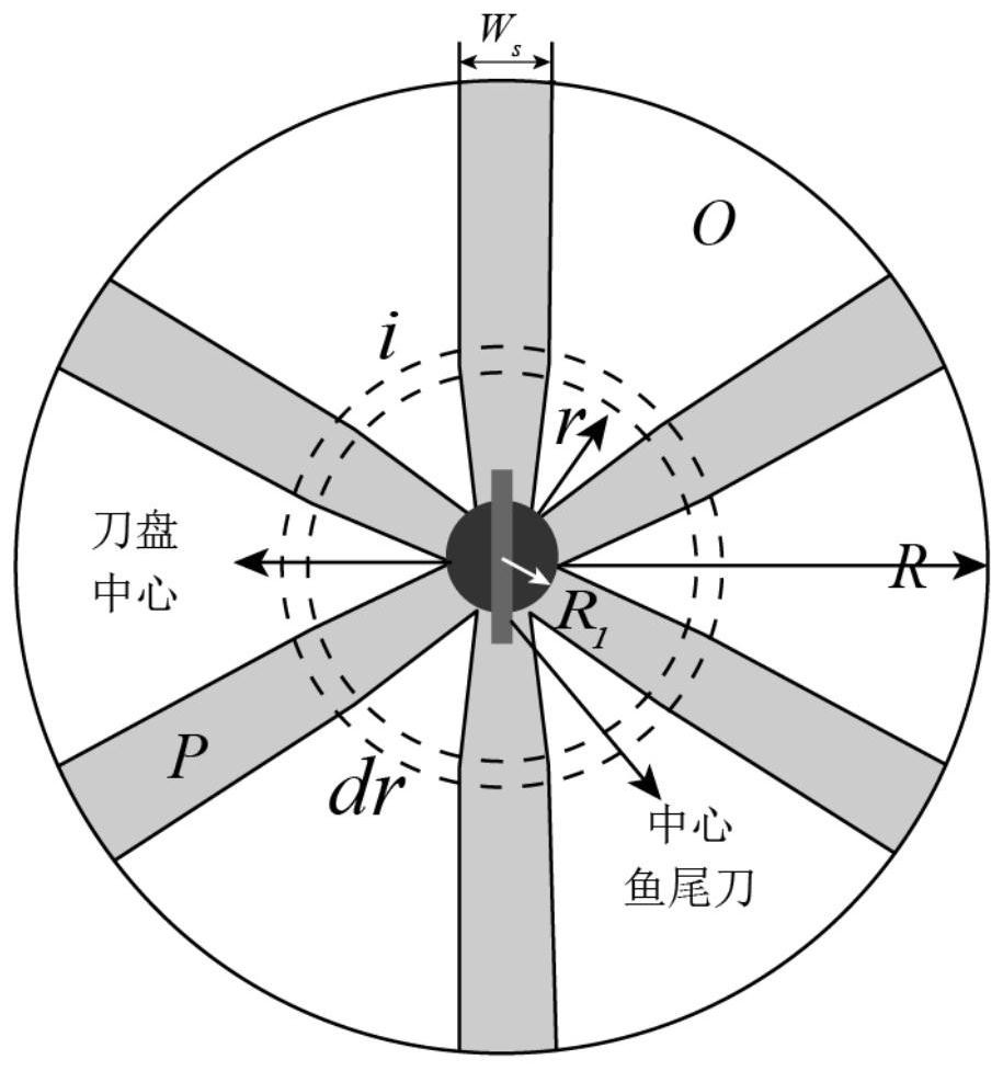
[0095] Step (1): Simplify the cutterhead model. According to the actual configuration of the shield cutter head of this project, scrapers, hobs, cutters, profiling knives and other knives outside the central area of ​​the shield are removed, and the panel, spokes and center large-sized fishtail knife are retained to form a simplified calculation diagram of the cutter head Such as Image 6 shown.

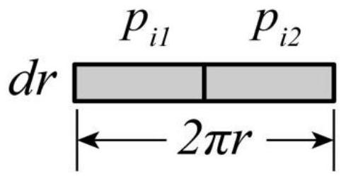
[0096] Step (2): Take ring differential for the cutterhead model. Divide the circular cutter head into circular microelements, each microelement thickness is dr, and the radius of the circular microelement is r; if the ring microelement width dr is in...

Embodiment 2

[0119] The radial plate shield cutter head used in the construction of a cross-sea tunnel project in Guangdong is used as an example to illustrate.

[0120] A method for predicting surface subsidence of a shield excavation face considering the formation deformation caused by cutter head extrusion, comprising the following steps:

[0121] Step (1): Simplify the cutter head model. In view of the actual configuration of the shield cutter head of this project, scrapers, hobs, cutters, profiling knives and other knives outside the central area of ​​the shield are removed, and the panel, spokes and center hob of the cutter head are retained to form a simplified calculation diagram of the cutter head. Figure 7 shown.

[0122] Step (2): Take a circular micro-element for the cutter head, each micro-element has a thickness of dr, and the distance between the ring and the center is r; expand the micro-element circle to approximate a rectangular micro-element with a length of 2πr and a ...


PUM


Abstract

The invention discloses a method for predicting ground surface subsidence of a shield excavation face considering the deformation of the stratum squeezed by the cutter head. The extrusion time, extrusion displacement, and soil deformation volume caused by cutterhead extrusion during the excavation process can be quantitatively expressed by the excavation parameters such as cutterhead speed and shield excavation speed. As an important factor affecting the surface settlement, the extrusion deformation, together with the over-under-excavation formation loss caused by the unbalanced excavation and discharge of the shield, improves the ability of the classic Peck formula to predict the surface settlement at the excavation face during the shield tunneling process. . The invention is applicable to any type of circular cutter head, and the implementation process is clear and simple, which can further improve the prediction accuracy of ground surface settlement caused by shield excavation under the existing calculation framework, and provide a basis for fine control of shield tunneling.

Description

technical field [0001] The invention belongs to the field of shield tunnel engineering, and in particular relates to a method for predicting ground surface settlement of a shield excavation face in consideration of deformation of strata squeezed by a cutter head. Background technique [0002] As a professional tunnel excavation equipment, shield machine is widely used in urban tunnel construction because of its relatively safe and environmentally friendly construction, as well as fast economy. However, with the rapid development of shield tunneling, the engineering hydrogeology and surrounding environment encountered are becoming more and more complex, and accidents caused by shield tunneling are not uncommon. Among them, the surface deformation caused by tunnel excavation, as the core issue that needs to be controlled in shield construction, has been widely concerned for a long time, but it is rarely concluded. [0003] On the whole, the ground surface subsidence that occu...

Claims


Application Information

Patent Timeline
Patent Type & Authority Patents(China)
IPC IPC(8): G06F30/13G06F30/20
CPCG06F30/13G06F30/20
Inventor 瞿同明王树英王海波
Owner CENT SOUTH UNIV
Learn More