Blood coagulation detection chip and electrochemical sensor
A detection chip and coagulation technology, applied in the field of coagulation detection, can solve the problems of large size of detection instruments, poor light transmittance, affecting the accuracy of detection results, etc., and achieve the effects of rapid prognosis evaluation, high accuracy, and rapid drug efficacy monitoring
- Summary
- Abstract
- Description
- Claims
- Application Information
AI Technical Summary
Problems solved by technology
Method used
Image
Examples
Embodiment 1
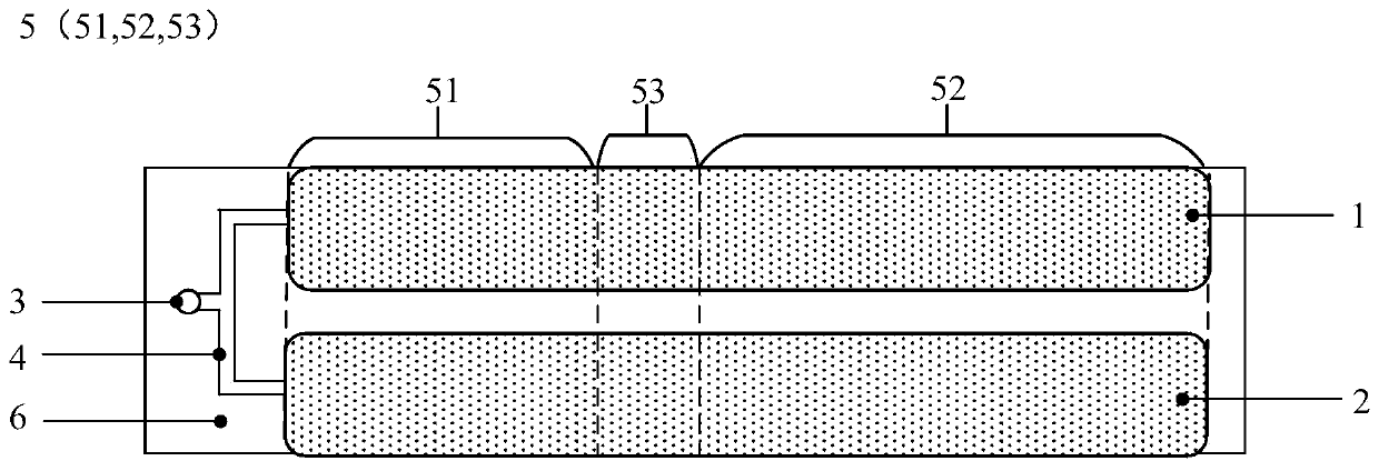
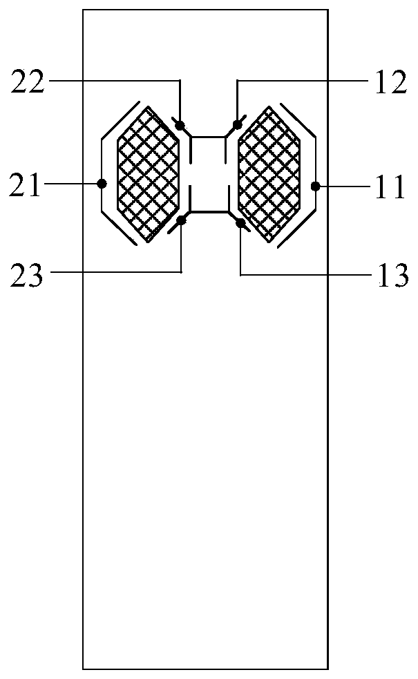
[0077] This embodiment provides a blood coagulation detection chip, and the surface of the blood coagulation detection chip forms the detection area 5 of the sample to be tested. Along the flow direction of the sample to be tested, the detection area 5 is divided into a first working area 51 , a transition area 53 and a second working area 52 connected in sequence. Such as figure 1 As shown, the coagulation detection chip includes a sample inlet 3 , a first detection channel 1 and a second detection channel 2 . Wherein, the sampling port 3 is provided at one end of the coagulation detection chip close to the first working area 51, the sampling port 3 is connected to the sampling channel 4, and the end of the sampling channel 4 away from the sampling port 3 forms two independent first communication channels. The first communication port is connected to the first detection channel 1, and the second communication port is connected to the second detection channel 2. After the sa...
Embodiment 2
[0093] This embodiment provides a blood coagulation detection chip, which differs from the blood coagulation detection chip provided in Example 1 in that:
[0094] The driving member 8 includes a hydrophilic part disposed in the first working area 51 and the second working area 52 , and a hydrophobic part disposed in the transitional area 53 . Since the first working area 51 is provided with a hydrophilic part, and the transition area 53 is provided with a hydrophobic part, when the blood sample flows from the first working area 51 to the transition area 53, the flow velocity becomes slow, thereby limiting the flow of the blood sample. When the blood sample flows from the transition area 53 to the second working area 52, since the second working area 52 is provided with a hydrophilic part, the blood sample flows from the hydrophobic area to the hydrophilic area, and the flow velocity increases, and finally the blood sample flows through the first The speed V of the working are...
Embodiment 3
[0096] This embodiment provides a blood coagulation detection chip, which differs from the blood coagulation detection chip provided in Example 1 in that:
[0097] Such as Figure 9 As shown, the driver 8 includes a required number of flow limiting components located in the first working area 51 , and a required number of microhole components located in the transitional area 53 and the second working area 52 . Wherein, the restrictor assembly includes a first restrictor 81 and a second restrictor 82, the first restrictor 81 and the second restrictor 82 have a first opening and a second opening along the direction of blood flow, the first The diameter of the opening is larger than the diameter of the second opening. The microhole assembly includes a required number of microholes 83 opened in the transition region 53 and the second working region 52 . When the blood sample flows into the flow limiting component, it flows in through the first opening, and then flows out through...
PUM
 Abstract
Description
Claims
Application Information
 - R&D
- Intellectual Property
- Life Sciences
- Materials
- Tech Scout
- Unparalleled Data Quality
- Higher Quality Content
- 60% Fewer Hallucinations
Browse by: Latest US Patents, China's latest patents, Technical Efficacy Thesaurus, Application Domain, Technology Topic, Popular Technical Reports.
© 2025 PatSnap. All rights reserved.Legal|Privacy policy|Modern Slavery Act Transparency Statement|Sitemap|About US| Contact US: help@patsnap.com


