Atomizing pump head

A technology of spray pump and nozzle head, which is applied in the field of spray pump head, which can solve the problems of fast liquid flow, affecting user experience, pressure difference, etc., achieves the effect of fewer parts, convenient processing, and helpful spring reset

Inactive Publication Date: 2019-07-26
沈利庆
View PDF2 Cites 4 Cited by
  • Summary
  • Abstract
  • Description
  • Claims
  • Application Information

AI Technical Summary

Problems solved by technology

[0006] However, the pump core still has some deficiencies. First, its upper channel has a smaller structure, and the liquid flows faster between the upper and lower channels. When the pressure in the upper channel is released, the liquid in the lower channel goes up quickly, replenishing In the channel on the road, there is a pressure difference between the upper and lower channels, which will form a spray again, which will affect people's use experience
[0007] Second, after its lower channel is formed by pressing to the maximum, it will maintain a relatively high pressure after spraying. At this time, release the finger pressure. During the spring reset process, the pressure will still exert pressure on the liquid inlet pump at the lower end of the pump core. The beads generate pressure, which affects the speed and amount of liquid entering, making it difficult for the liquid to be completely filled after the pump core is reset, and a small amount of air will be mixed in
Affects user experience

Method used


Image

  • Atomizing pump head
  • Atomizing pump head
  • Atomizing pump head

Examples


Embodiment Construction

[0030] Embodiments of the present invention will be further described below in conjunction with the accompanying drawings.

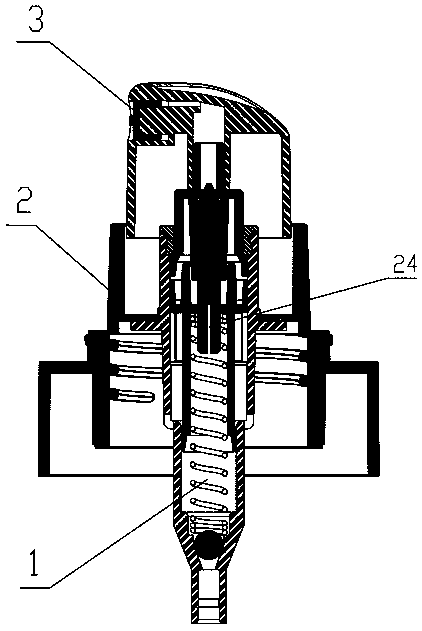
[0031] The invention relates to a high-efficiency spray pump head, such as figure 1 As shown, it consists of a pump core 1, a middle cover 2, and a nozzle head 3. The pump core is fixed in the center of the middle cover, and the nozzle head is set on the upper side of the middle cover, and moves up and down relative to the middle cover. The nozzle head is connected with a spray channel, and the lower part of the pump core is stretched under the liquid level of the bottle cavity through a flexible pipe.

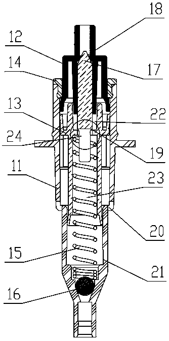
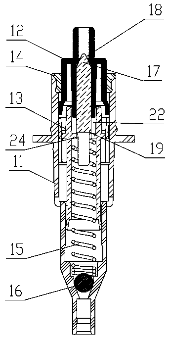
[0032] like figure 2 As shown, the pump core includes a pump core main body 11, an upper piston 12, a reverse thrust plug 13, a sealing ring 14, etc., the pump core main body is a hollow barrel-shaped structure with a multi-layer stepped structure, the pump core main body and the upper piston, reverse thrust The plug is slidingly fitted, and the anti-...


PUM


Abstract

The invention relates to an atomizing pump head capable of controlling spray mist pressure to be uniform. The atomizing pump head consists of a pump core, a middle cover and a nozzle head. The pump core is composed of a pump core body, an upper piston, a back pushing plug, a sealing ring and the like. An upper chamber is formed between the back pushing plug and the upper piston. A back pushing plug body is arranged at the center of the upper portion of the back pushing plug, and a cone body is arranged at the top of the back pushing plug. A round table surface is arranged at the center of theupper piston and is further matched with the cone body of a back pushing pillar to form a reverse check valve. A connecting groove is formed in the center of the piston, and a lower chamber and the upper chamber are connected through the connecting groove. A damping hole is formed in the tail end of the connecting groove. The cross sectional area of the bottom of the upper chamber is larger than that of the top of the lower chamber. A pressure relief hole is formed in the lower chamber of the pump core body of the atomizing pump head, and a pressure relief groove is formed in the lower half section of the lower chamber. The spray mist pressure of the atomizing pump head is not influenced by the action speed and force magnitude of fingers, a good mist spraying effect can be stably achievedand the phenomenon of water running at a nozzle opening is avoided.

Description

technical field [0001] The invention relates to the field of household articles, in particular to a spray pump head capable of controlling uniform spray pressure. Background technique [0002] In the field of household products such as cosmetics, washing products, and plant cultivation, the spray pump head is a very common auxiliary accessory for liquid containers. It is used to press the liquid in the bottle to let the mixed fluid of air and liquid flow out of the small hole quickly. The pressure near the small hole is small, and the air pressure above the liquid surface in the container is strong, and the liquid flows along the bottom of the small hole. The thin tube rises up, and after flowing out from the upper opening of the thin tube, it is impacted by the air flow and spreads in the air in the form of spray to form small particles of air suspension. [0003] The current relatively mature spray pump head is provided with a patent No. CN201521117894.9 "a new type of sp...

Claims


Application Information

Patent Timeline
Patent Type & Authority Applications(China)
IPC IPC(8): B65D47/34
CPCB05B11/1025B05B11/1066B05B11/1073
Inventor 沈利庆
Owner 沈利庆
Why Eureka
Try Eureka