Motor vehicle door lock

A motor vehicle door lock and locking technology, which is applied to vehicle locks, building locks, mechanical equipment, etc., can solve problems such as undesired opening, and achieve good functional safety.

Active Publication Date: 2017-03-15
KIEKERT AG
View PDF1 Cites 0 Cited by
  • Summary
  • Abstract
  • Description
  • Claims
  • Application Information

AI Technical Summary

Problems solved by technology

This can still lead to an undesired opening during the crash process under certain circumstances

Method used


Image

  • Motor vehicle door lock
  • Motor vehicle door lock
  • Motor vehicle door lock

Examples


Embodiment Construction

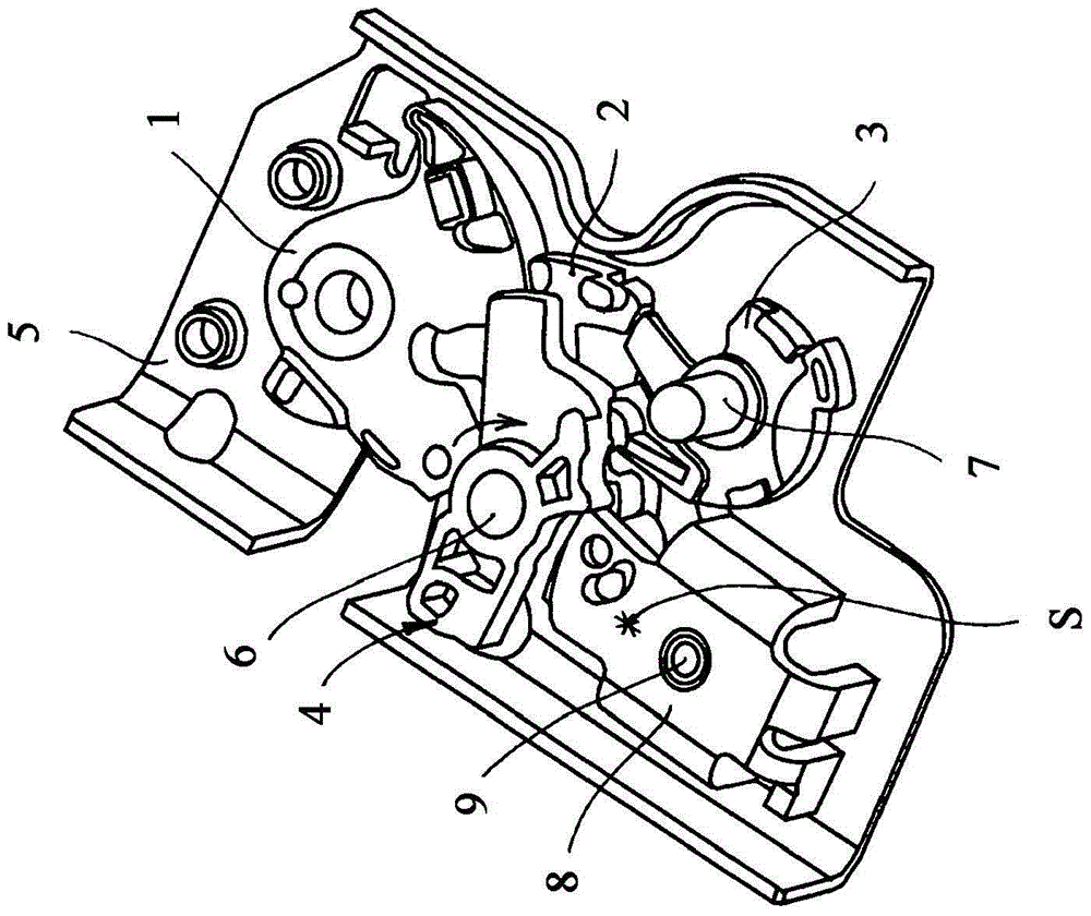
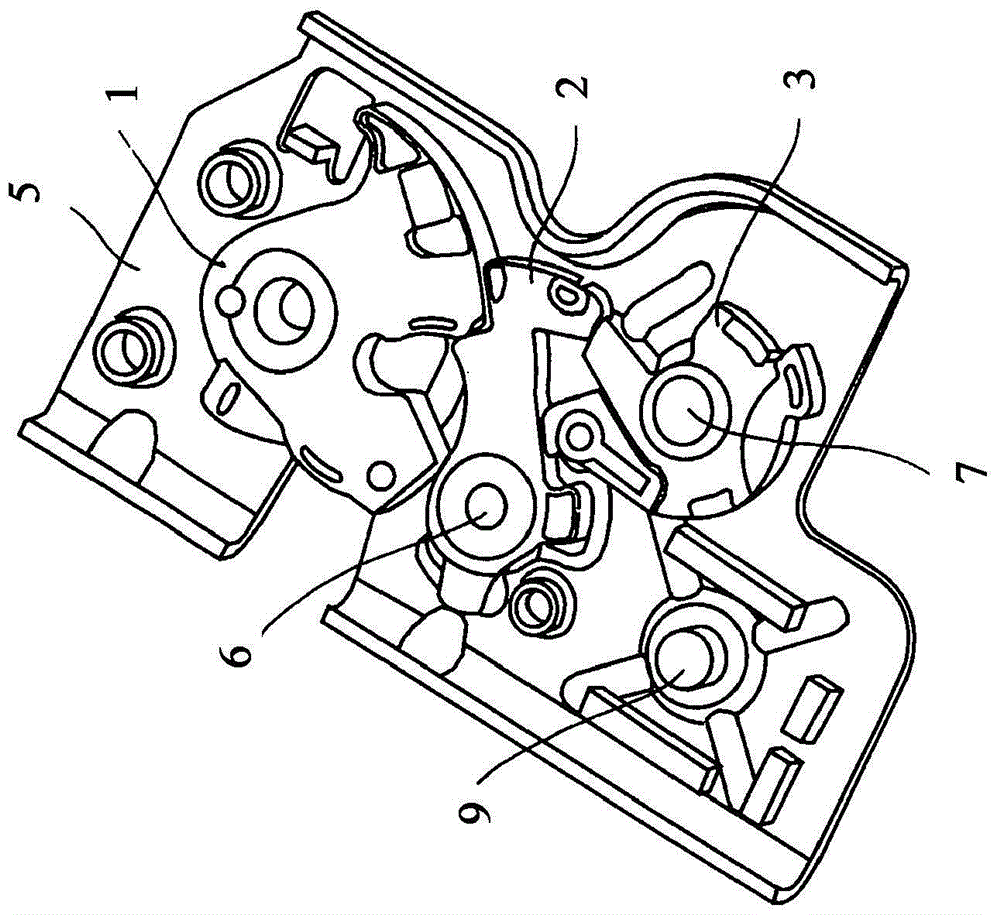
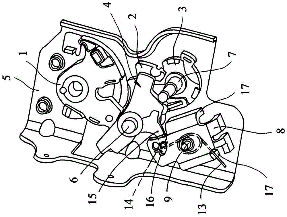
[0024] The drawing shows a motor vehicle door lock, which is normally equipped with locking mechanisms 1 , 2 , 3 . The locking mechanism 1 , 2 , 3 consists of a rotary locking fork 1 and, in the exemplary embodiment, two locking pawls 2 , 3 . The pawl 3 here assumes the actual locking function. On the other hand, the locking pawl 2 is designed as a so-called comfort pawl. However, in the present invention the comfort paw is not very important, so the details relating to this particular design are not explained in detail.

[0025] Crucially, for example in Figure 1A with 1B The locking mechanism 1 , 2 , 3 in the main locking position can be opened by lifting the pawl 2 , 3 from the rotary locking fork 1 . As a result, the latch (not explicitly shown) previously held by the rotary lock 1 is released, so that the associated motor vehicle door can be opened. In order to lift the pawls 2, 3 from the rotary lock 1 or to activate the locking mechanism 1, 2, 3, an actuating lever...


PUM


Abstract

The invention relates to a motor vehicle door lock having a locking mechanism (1, 2, 3), at least one actuating lever (4) for triggering the locking mechanism (1, 2, 3) and a pivotable shaft (9 ) swings the locking lever (8). The locking lever (8) causes the locking mechanism (1, 2, 3) to invalidated. According to the invention, the locking lever (8) is mounted eccentrically on its shaft (9) and thus generates a counter moment (M) that locks the actuating lever (4) as a function of the decelerating force (F) that occurs.

Description

technical field [0001] The invention relates to a motor vehicle door lock comprising a locking mechanism, at least one actuating lever for triggering the locking mechanism and a pivotable locking lever, which locking lever is at least - for example in the event of an accident ("collision accident") ”)—in the event of a decelerating force of predetermined magnitude and direction, the locking mechanism is rendered ineffective. Background technique [0002] Locking mechanisms generally typically consist of a rotary yoke and pawl. In the event of a deceleration force with a predetermined magnitude and direction occurring in connection with an accident, there is fundamentally a risk that the locking mechanism will be unintentionally released, since the deceleration force acts on the actuating lever for triggering the locking mechanism. The locking lever, which disables the locking mechanism under the decelerating force with a predetermined magnitude and direction, prevents such ...

Claims


Application Information

Patent Timeline
Patent Type & Authority Patents(China)
IPC IPC(8): E05B77/04E05B85/26
CPCE05B77/06E05B85/26Y10T292/108E05B85/243E05B79/10
Inventor K·哥特岑C·富赫斯
Owner KIEKERT AG
Why Eureka
Try Eureka