Shoulder joint working method based on bionic structure

A working method and shoulder joint technology, applied in the field of bionic machinery, can solve the problems of insufficient lightness in structure, large volume and difficult operation, and achieve the effects of simple and novel structure, simple operation and convenient operation.

Active Publication Date: 2019-07-26
SHANDONG UNIV OF SCI & TECH
View PDF9 Cites 0 Cited by
  • Summary
  • Abstract
  • Description
  • Claims
  • Application Information

AI Technical Summary

Problems solved by technology

[0003] At present, in the field of robotic arms, robotic arms are generally large in size, heavy in weight, light in structure, flexible in use, and large in working space, which seriously affects the use of disabled people.
[0004] The Chinese patent document with the publication number CN104908060A proposes a five-degree-of-freedom parallel bionic shoulder joint, which realizes the movement of the shoulder joint in a three-dimensional plane. However, the mechanism is too complicated, and the volume is inevitably too large. The difference is so far that it cannot be used on artificial limbs; the Chinese patent document with the publication number CN101301755A proposes a 3-DOF spherical parallel bionic shoulder joint with offset output. Although this technology is small in size, the parallel mechanism is complicated to control. If you use On prosthetics, it is not easy for the disabled to achieve precise control

Method used


Image

  • Shoulder joint working method based on bionic structure
  • Shoulder joint working method based on bionic structure
  • Shoulder joint working method based on bionic structure

Examples


Embodiment 1

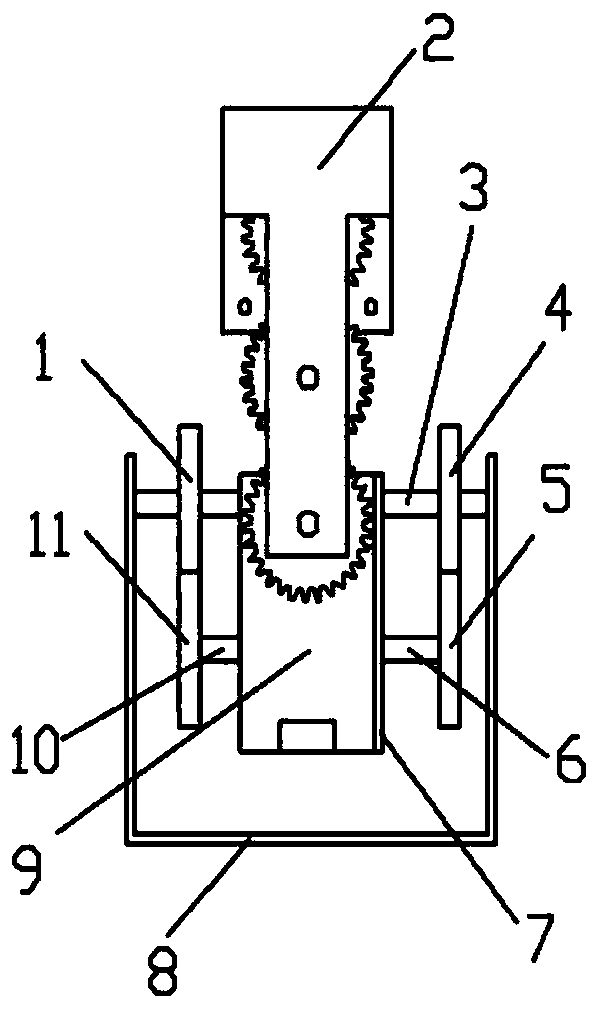
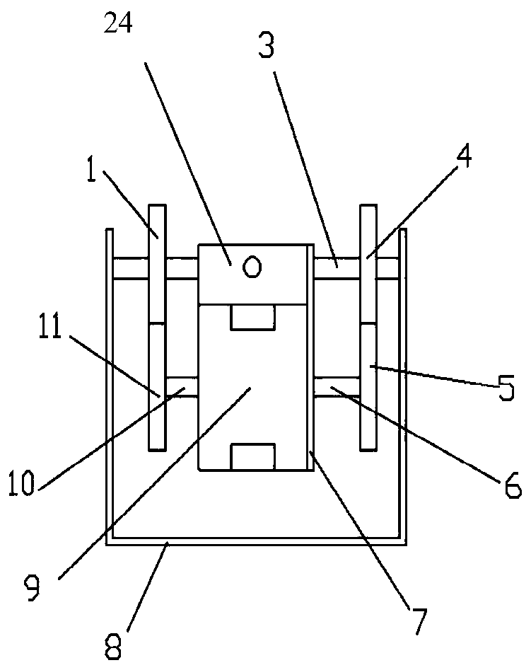
[0035] A shoulder joint working method based on a bionic structure, based on a bionic shoulder joint mechanism, the bionic shoulder joint mechanism includes a flexion and extension device and an extension and extension device; the flexion and extension device includes two symmetrically arranged T-shaped plates 2, two T-shaped plates 2 An end plate is arranged between, and an upper gear set is arranged on the end plate, and the upper gear set includes two gears meshing in sequence, and a first motor 16 is arranged on the end plate, and the first motor 16 is connected with the gear at the top of the upper gear set; The stretching device includes a U-shaped connecting plate 8, and the U-shaped connecting plate 8 is provided with a connecting block 24, a second motor 9 and a lower gear set. The lower gear set includes two meshing gears, and the connecting block includes four sides, two of which One opposite side is connected with the terminal gear of upper gear set by rotating shaf...

Embodiment 2

[0040]A shoulder joint working method based on a bionic structure, the steps of which are as described in Embodiment 1, the difference is that the upper gear set of the bionic shoulder joint mechanism includes three sequentially meshed gears, and the gear at the top of the upper gear set rotates , driving the three gears meshing in turn to rotate. Three gears are provided to increase the motion angle of the ball joint mechanism, which can prevent motion interference during the flexion and extension of the ball joint. Setting too many gears will reduce the transmission efficiency and increase the mass and volume of the mechanism.

Embodiment 3

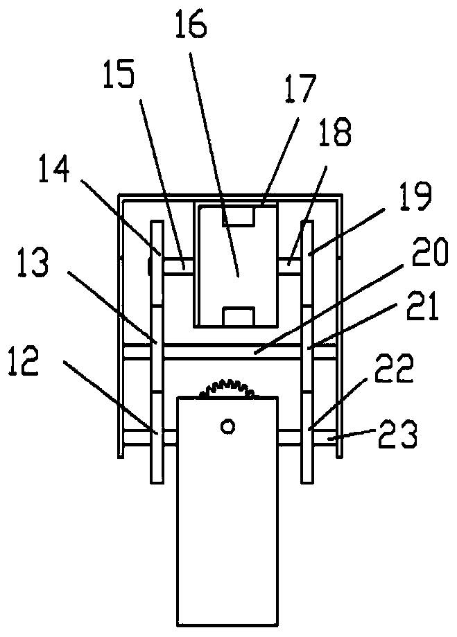
[0042] A shoulder joint working method based on a bionic structure, its steps are as described in Embodiment 2, the difference is that the number of upper gear sets on the end plate of the bionic shoulder joint mechanism is two rows, and one row of upper gear sets is vertical The first gear 14, the third gear 13, and the fifth gear 12 are arranged in the direction, and the second gear 19, the fourth gear 21, and the sixth gear 22 are vertically arranged on the other row of upper gear sets; the first motor includes the first output of the first motor Shaft 15 and the second output shaft 18 of the first motor, the first output shaft 15 of the first motor is connected with the first gear 14, and the second output shaft 18 of the first motor is connected with the second gear 19, as figure 2 shown.

[0043] When the first motor is driven, the two output shafts of the first motor rotate simultaneously, driving the first gear and the second gear to rotate, the first gear drives the ...


PUM


Abstract

The invention relates to a shoulder joint working method based on a bionic structure, and belongs to the technical field of bionic machinery. A bending device and a stretching device are included; thebending device comprises two symmetrically-arranged T-shaped plates, an upper gear set and a first motor, the upper gear set includes at least two gears which are sequentially meshed, the first motordrives the upper gear set to rotate, and the stretching device is driven to rotate; the stretching device includes a U-shaped connecting plate, and the U-shaped connecting plate is internally provided with a connecting block, a second motor and a lower gear set, the lower gear set includes two meshed gears, and the connecting block includes four sides, wherein two opposite sides are connected tothe gears at the tail end of the upper gear set through rotating shafts, and the other two opposite sides are connected to the gears at the top end of the lower gear set through rotating shafts; the second motor drives the lower gear set to rotate, the U-shaped connecting plate is driven to rotate, bending and stretching motion of the human joint are simulated, three-freedom-degree movement of a joint of a mechanical arm is achieved, the volume of the joint of the mechanical arm is reduced, and the practicability is high.

Description

technical field [0001] The invention relates to a working method for a shoulder joint of an artificial limb, and belongs to the technical field of bionic machinery. Background technique [0002] Every year, due to natural disasters, war injuries, congenital and other reasons in the world, people will be physically disabled, and physical disabilities will bring inconvenience to the lives of the disabled. To provide good services for the disabled is a noble act of good deeds. cause. [0003] At present, in the field of robotic arms, robotic arms are generally large in size, heavy in weight, light in structure, flexible in use, and large in working space, which seriously affects the use of disabled people. [0004] The Chinese patent document with the publication number CN104908060A proposes a five-degree-of-freedom parallel bionic shoulder joint, which realizes the movement of the shoulder joint in a three-dimensional plane. However, the mechanism is too complicated, and the ...

Claims


Application Information

Patent Timeline
Patent Type & Authority Applications(China)
IPC IPC(8): B25J17/02
CPCB25J17/02
Inventor 王传江陈晨江浩孙秀娟樊炳辉王恒刘汉进赵宪正周健博
Owner SHANDONG UNIV OF SCI & TECH
Why Eureka
Try Eureka