Reagent sequential loading device, centrifugal microfluidic device and analysis system

A loading device and reagent technology, applied in biological testing, material inspection products, laboratory equipment, etc., can solve the problems of increasing the difficulty of instrument design, increasing the cost of chip processing, increasing the cost of microfluidic chip processing, etc.

Active Publication Date: 2019-07-23
深圳市呈晖医疗科技有限公司
View PDF7 Cites 8 Cited by
  • Summary
  • Abstract
  • Description
  • Claims
  • Application Information

AI Technical Summary

Problems solved by technology

However, the use of valves often increases the processing cost of the entire microfluidic chip, and the sequential loading achieved by valves is often difficult to guarantee repeatability and reliability.
Moreover, in centrifugal microfluidics, the realization of these valves is not easy
The capillary valve has high requirements on the machining accuracy of the pipe, and the capillary valve itself is related to the contact angle of the liquid reagent on the surface of the material. Often different reagents require different pipe sizes to achieve the effect of the capillary valve; the siphon valve needs to be made on the siphon pipe Hydrophilic treatment, which requires high process requirements, often greatly increases the processing cost of the chip; the melting of paraffin in the paraffin valve often requires the corresponding temperature control of the instrument, which increases the difficulty of instrument design

Method used


Image

  • Reagent sequential loading device, centrifugal microfluidic device and analysis system
  • Reagent sequential loading device, centrifugal microfluidic device and analysis system
  • Reagent sequential loading device, centrifugal microfluidic device and analysis system

Examples


Embodiment Construction

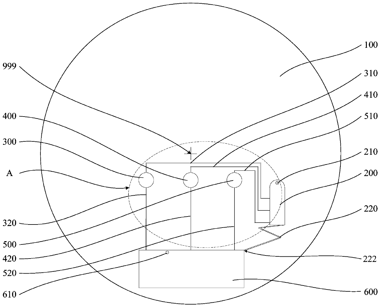
[0018]In order to make the above-mentioned purposes, features and advantages of the present application more obvious and understandable, the specific implementation manners of the present application will be described in detail below in conjunction with the accompanying drawings. In the following description, numerous specific details are set forth in order to provide a thorough understanding of the present application. But the application can be implemented in many other ways that are different from those described here, and those skilled in the art can make similar improvements without departing from the connotation of the application, so the application is not limited by the specific embodiments disclosed below. In one embodiment of the present application, a reagent sequential loading device has a center of rotation and the reagent sequential loading device includes a liquid outlet pipeline, a liquid control chamber, a collection chamber and at least two loading chambers; t...


PUM

PropertyMeasurementUnit
radiusaaaaaaaaaa
lengthaaaaaaaaaa
widthaaaaaaaaaa

Abstract

The present application relates to a reagent sequential loading device, a centrifugal microfluidic device and an analysis system. The reagent sequential loading device comprises a liquid discharging pipe, a liquid control chamber, a collecting chamber and at least two loading chambers; the liquid discharging pipe communicates with the liquid control chamber and the collecting chamber, and the liquid discharging pipe is equipped with a resistance increasing structure; the loading chamber is provided with a liquid control pipe and a loading pipe; the collecting chamber is provided with a collecting chamber hole, the liquid control chamber is provided with a liquid injection hole, and the distances between each communicating end and the liquid injection hole are different; and the distance from the rotation center is arranged in an order from small to large: the position where the loading chamber communicates with the liquid control pipe, the loading chamber, and the position where the loading chamber communicates with the loading pipe thereof. The implementation is simple, the design difficulty is reduced and the processing cost is saved; the centrifugal speed can be controlled, so that the time interval of loading different reagents is controlled, and time is reserved for reagent reaction or reagent treatment; and by adjusting different reagents in different loading chambers cansequential loading of any reagent be realized.

Description

technical field [0001] The present application relates to the field of centrifugal microfluidics, in particular to a reagent sequential loading device, a centrifugal microfluidic device and an analysis system. Background technique [0002] Microfluidics refers to the manipulation of liquids on the submillimeter scale, where the submillimeter scale is generally several microns to hundreds of microns. Microfluidic technology integrates the basic operating units involved in the fields of biology and chemistry, and even the functions of the entire laboratory, including sampling, dilution, reaction, separation, detection, etc., on a small chip, so it is also called lab-on-a-chip ( Lab-on-a-Chip). This kind of chip is generally composed of various liquid reservoirs and interconnected microchannel networks, which can greatly reduce the sample processing time, and realize the maximum utilization efficiency of reagent consumables through precise control of liquid flow. Microfluidic...

Claims


Application Information

Patent Timeline
Patent Type & Authority Applications(China)
IPC IPC(8): G01N33/50B01L3/00
CPCG01N33/50B01L3/5027
Inventor 汤明辉
Owner 深圳市呈晖医疗科技有限公司
Why Eureka
Try Eureka