Down-conversion method of ultra-low additional phase noise millimeter wave signal source

A phase noise and millimeter wave technology, which is applied in spectrum analysis, measurement of electrical variables, multi-frequency modulation transformation, etc., can solve the problems of reducing the phase noise accuracy of millimeter wave signal sources and the phase noise of local oscillator signals of limited frequency converters, etc. , to achieve the effect of improving measurement accuracy, high measurement accuracy and reducing error

Inactive Publication Date: 2019-07-19
成都天奥技术发展有限公司 +1
View PDF5 Cites 6 Cited by
  • Summary
  • Abstract
  • Description
  • Claims
  • Application Information

AI Technical Summary

Problems solved by technology

The existing down conversion methods mainly include direct frequency conversion method and harmonic mixing frequency conversion method, these methods are limited by the phase noise of the local oscillator signal of the down converter
During the phase noise test of the ultra-low phase noise millimeter wave signal source, the phase noise of the local oscillator signal of the down-converter cannot be much better than the phase noise of the measured millimeter-wave signal, so that additional phase noise is introduced during the down-conversion process Too large will reduce the accuracy of phase noise measurement of mmWave signal sources

Method used


Image

  • Down-conversion method of ultra-low additional phase noise millimeter wave signal source
  • Down-conversion method of ultra-low additional phase noise millimeter wave signal source
  • Down-conversion method of ultra-low additional phase noise millimeter wave signal source

Examples


Embodiment Construction

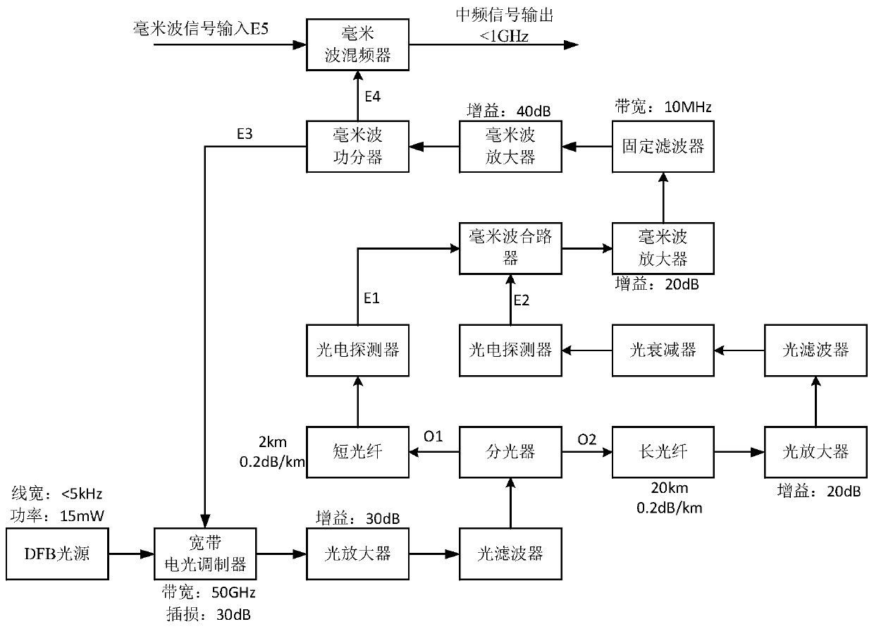
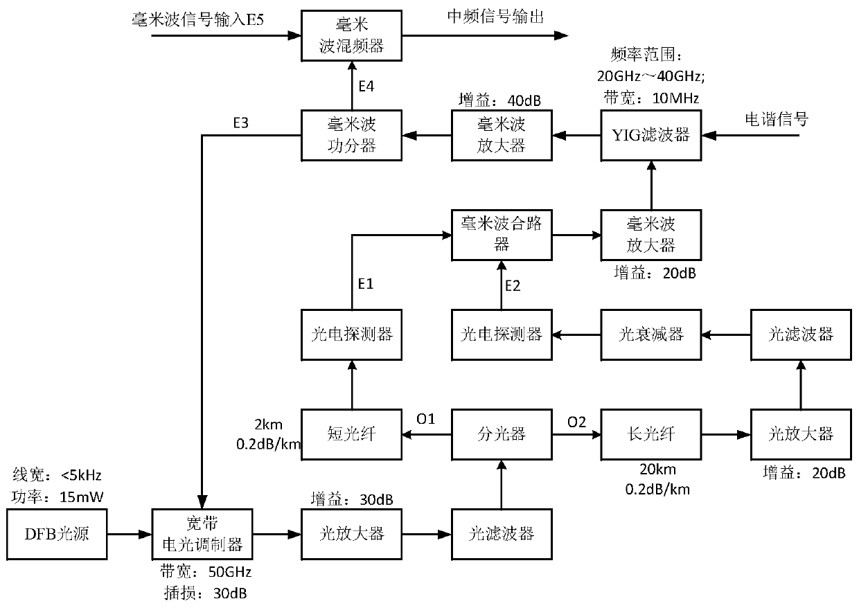
[0014] refer to figure 1 . According to the present invention, the DBF light source with a narrow linewidth is modulated by a broadband photoelectric modulator, and after being amplified by a broadband photoelectric modulator, an optical amplifier and filtered by an optical filter, it is divided into two optical signals by an optical splitter, and one of them is sent to the first optical signal through a short optical fiber. One photodetector is converted into an electrical signal; the other is sent to the second photodetector through a long optical fiber, an optical amplifier, an optical filter and an optical attenuator to be converted into an electrical signal, and the two electrical signals are synthesized into one by a millimeter wave combiner, and then After being amplified by the millimeter-wave amplifier and filtered by the filter, the millimeter-wave power divider is divided into two millimeter-wave signals, one of which is input to the electrical input interface of th...


PUM


Abstract

The invention discloses a down-conversion method of an ultra-low additional phase noise millimeter wave signal source. The utility model aims to provide the millimeter wave signal down-conversion method with low additional phase noise and high phase noise measurement accuracy. According to the technical scheme, a broadband intensity modulator is used for modulating a DBF light source, the DBF light source is divided into two optical signals after being amplified by an optical amplifier and filtered by an optical filter, and one optical signal is sent to a first photoelectric detector through ashort optical fiber to be converted into an electric signal; the other path is sent to a second photoelectric detector through a long optical fiber, an optical amplifier, an optical filter and an optical attenuator and is converted into an electric signal; wherein the two paths of electric signals are combined into one path through the millimeter wave combiner, then the electric signals are divided into two paths of millimeter wave signals through the millimeter wave power divider after passing through the millimeter wave amplifier and the filter, and one path of electric signals is input into an electric input interface of the broadband photoelectric modulator to form a photoelectric loop; and the other path of signal is input to a local oscillator input port of the millimeter wave mixerand is mixed with a millimeter wave signal needing to be down-converted to obtain an intermediate frequency signal.

Description

technical field [0001] The invention relates to a millimeter-wave ultra-low phase noise frequency source calibration and a millimeter-wave signal down-conversion method applicable to the field of time-frequency measurement. More specifically, the present invention relates to a down-conversion method for millimeter-wave signals with a frequency range from 20 GHz to 40 GHz and an additional phase noise as low as -135 dBc / Hz. Background technique [0002] Millimeter wave is the electromagnetic spectrum with a wavelength between (1-10) mm, corresponding to a frequency range of (300-30) GHz. Millimeter waves are at the high end of the microwave band, with an upper limit adjacent to submillimeter waves and closer to light waves. From the perspective of frequency, the low-end of millimeter wave is connected with microwave, and the high-end is connected with infrared and light waves. Therefore, millimeter wave has gradually developed into a comprehensive branch of microwave and opt...

Claims


Application Information

Patent Timeline
Patent Type & Authority Applications(China)
IPC IPC(8): H03D7/16G01R23/165
CPCH03D7/16G01R23/165
Inventor 梁桂海沈世科胡丹丹潘柳王毅
Owner 成都天奥技术发展有限公司
Why Eureka
Try Eureka