Winding structure and winding method of transformer coil

A technology of transformer coils and winding methods, which is applied in the field of transformer manufacturing, can solve problems such as space waste, and achieve the effects of reducing waste, reducing consumption, and reducing no-load loss

Inactive Publication Date: 2019-07-19
JIANGSU RYAN ELECTRIC LTD BY SHARE LTD
View PDF6 Cites 0 Cited by
  • Summary
  • Abstract
  • Description
  • Claims
  • Application Information

AI Technical Summary

Problems solved by technology

[0004] In order to overcome the problem of unnecessary waste of space in the coil structure existing in the pr

Method used


Image

  • Winding structure and winding method of transformer coil
  • Winding structure and winding method of transformer coil

Examples


Embodiment 1

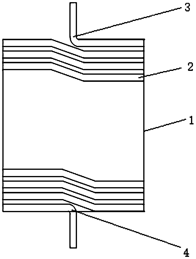
[0027] Please see figure 1 , is a structural schematic diagram of a preferred embodiment of a winding structure of a transformer coil in the present invention, a winding structure of a transformer coil includes a winding mold and a wire body, and the wire body is wound from the winding mold Winding from the end to the end, the wire body is wound clockwise along the direction from the winding end to the end. The wire body of the first turn forms an "S" bend at the winding end, and then the wire body winds a circle horizontally, and then turns Press a diagonal line at the bottom right, the vertical distance between the upper and lower ends of the diagonal line is the sum of the diameter of the wire body and the distance between each turn of the coil, then the wire body continues to wind a circle horizontally, and then press a diagonal line to the bottom right , parallel to the previous oblique line, the vertical distance between the upper end and the lower end of the oblique lin...

Embodiment 2

[0033] A method for winding a transformer coil, comprising the steps of:

[0034] a. Wind the first turn of the coil clockwise from top to bottom from the winding end to the end on the winding mold, and bend the wire body of the first turn at the winding end to form an "S" bend. Bend and wrap the insulating paper, and then wind the wire body horizontally to form the first turn from top to bottom;

[0035] b. At the "S" bend near the starting end of the first turn, draw a slash to the right and down. The vertical distance between the upper end and the lower end of the slash is the sum of the diameter of the wire body and the distance between the coils of each turn , wrap insulating paper at the upper and lower ends of the oblique line, place insulating supports at the upper and lower ends of the oblique line, and then continue winding the wire body horizontally to form the second turn from top to bottom;

[0036] c. Repeat step b to complete the winding of the intermediate coi...


PUM

PropertyMeasurementUnit
Thicknessaaaaaaaaaa

Abstract

The invention provides a winding structure of a transformer coil. The winding structure comprises a winding die and a wire body, wherein the wire body is wound from the start winding end of the winding die to the tail end, and the wire body from the start winding end to the tail end is wound clockwise; the wire body of the first turn is bent in an S shape at the start winding end, then the wire body is horizontally wound for a circle, and next, the wire body is bent for an oblique line towards the right lower side; the vertical distance between the upper end and the lower end of the oblique line is the sum of the diameter of the wire body and the distance between every turn of the coil, then the wire body is repeatedly and horizontally wound and wound downwards in an inclined mode until the tail end is reached, and the wire body is bent into an S shape and extended downwards in a vertical direction. According to the winding structure, the first turn wire at the end part is bent in an Sshape with a high wire, so that the spiral angle of a turn of wire is reduced; the end of each section is leveled, the height of the diameter of one wire body is reduced from calculation compared with that of a traditional structure, so that the height of the coil is reduced; under the condition that the insulation structure and the electrical distance are the same as those in the traditional structure, the height of an iron core window can be effectively reduced, the use amount of the iron core silicon steel sheet is reduced, and the no-load loss is reduced.

Description

technical field [0001] The invention relates to the technical field of transformer manufacturing, in particular to a winding structure of a transformer coil and a winding method thereof. Background technique [0002] In order to make the insulating material operate reliably within the safe voltage range, the coil is usually designed as a multi-segment multi-layer cylindrical structure with more than 2 segments to reduce its inter-layer voltage and inter-segment voltage, and an extra insulating material is placed between the layers And the method of opening the distance between segments to meet the technical requirements of the transformer's electrical strength. The higher the voltage, the more segments. However, the greater the number of segments, the greater the cumulative spacing between segments, which results in a higher axial height of the coil. As a result, the volume of the transformer increases, and the weight of silicon steel sheet, insulating material, steel and ...

Claims


Application Information

Patent Timeline
IPC IPC(8): H01F27/28H01F27/32H01F41/066H01F41/071H01F41/076H01F41/098H01F41/12
CPCH01F27/28H01F27/2828H01F27/323H01F27/324H01F41/122H01F41/125H01F41/066H01F41/071H01F41/076H01F41/098
Inventor 王良明梅德进徐伟薛桂兰
Owner JIANGSU RYAN ELECTRIC LTD BY SHARE LTD
Why Eureka
Try Eureka