A method for locating the shear failure position of rock structure plane in direct shear test

A technology of shear failure and positioning method, which is applied in the field of rock and soil mechanics, can solve the problems of damage acoustic emission source positioning, large positioning error, and inability to locate and analyze, and achieve high monitoring accuracy, high processing effectiveness, and fast search speed Effect

Active Publication Date: 2020-05-08
INST OF ROCK & SOIL MECHANICS CHINESE ACAD OF SCI
View PDF10 Cites 0 Cited by
  • Summary
  • Abstract
  • Description
  • Claims
  • Application Information

AI Technical Summary

Problems solved by technology

Chinese Patent Publication No. CN 102435980A, the publication date is 2012.05.02, and the title of the invention is "An Acoustic Emission Source or Microseismic Source Location Based on Analytical Solution". The location method does not require an iterative solution, but this method does not consider the elastic wave arrival time pickup error caused by the disturbance of the elastic wave propagation caused by the structural surface, so it cannot accurately locate the acoustic emission source of structural surface shear damage
[0006] (2) Some traditional acoustic emission monitoring and positioning methods require the acoustic emission source to be in the acoustic emission sensor array, otherwise the positioning results will not converge and the positioning error will be large
Due to the interference of the elastic wave on the structural surface, enclosing the sensor in the shear area will cause a time error, and it is impossible to accurately locate and analyze the shear damage position of the structural surface
Chinese Patent Publication No. CN106646375A Publication Date 2017.05.10, the title of the invention is "A Rock Acoustic Emission Source Location Method Based on ALL#FFT Phase Difference", the invention uses wavelet for acoustic emission denoising, and the denoised acoustic emission signal Use the ALL-FFT phase difference to calculate the phase difference, solve the phase difference, obtain the time delay estimation of the acoustic emission, and invert the coordinates of the acoustic emission source, but this invention is not applicable to the positioning situation when the acoustic emission source is outside the sensor array

Method used


Image

  • A method for locating the shear failure position of rock structure plane in direct shear test
  • A method for locating the shear failure position of rock structure plane in direct shear test
  • A method for locating the shear failure position of rock structure plane in direct shear test

Examples


Embodiment Construction

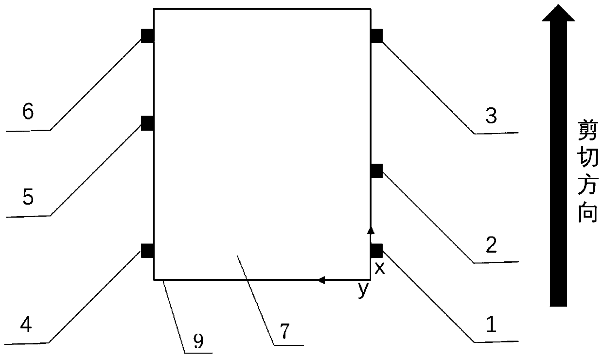
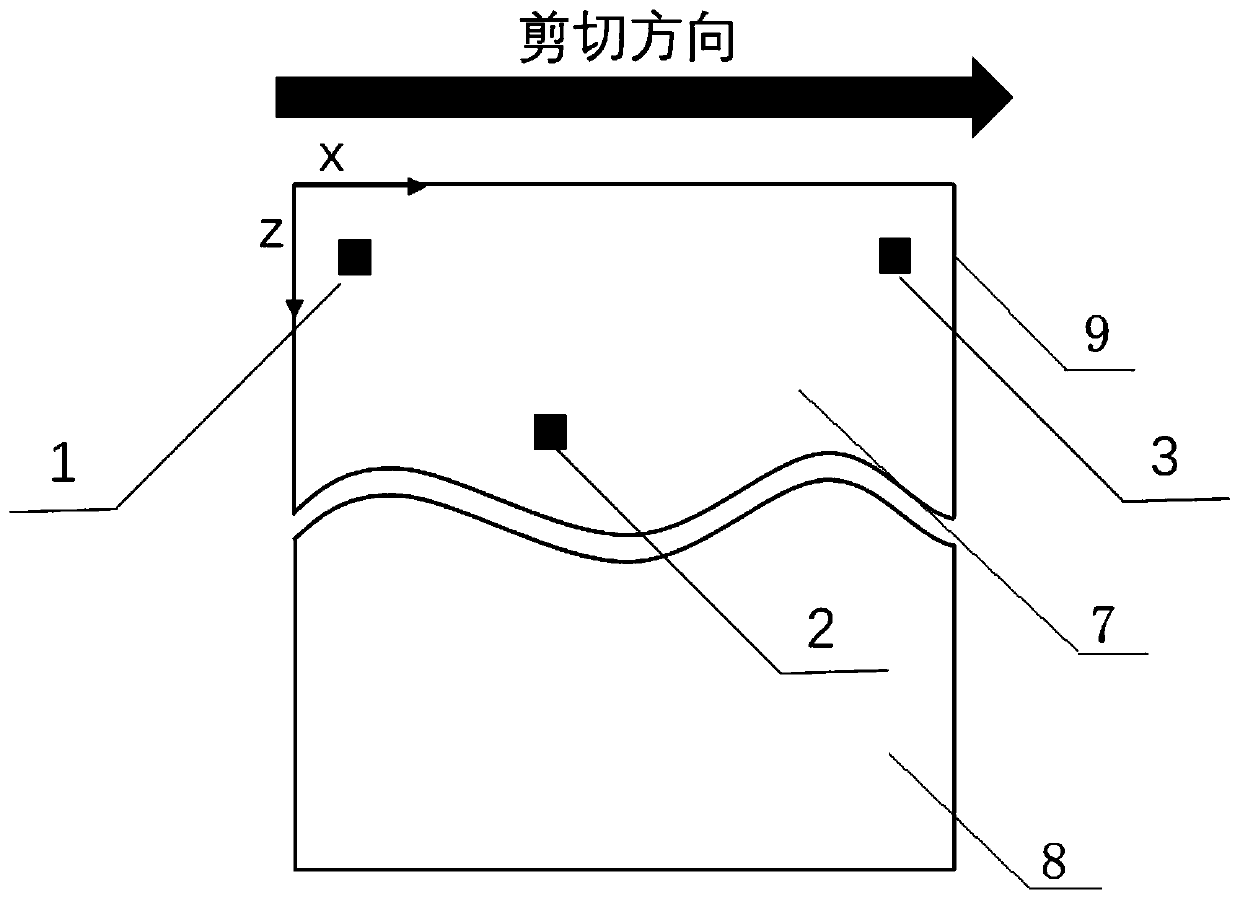
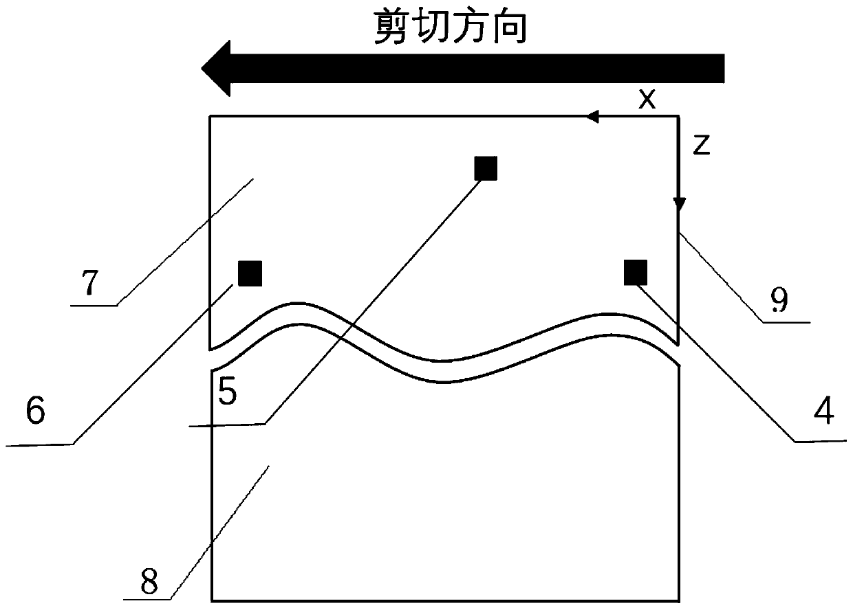
[0061] Combine below figure 1 , figure 2 , image 3 , Figure 4 , Figure 5 , Figure 6 , Figure 7 , Figure 8 , to further describe in detail the method of the present invention for locating the shear failure position of a block on a structural surface by using acoustic emission.

[0062] The present invention adopts acoustic emission to locate the optimization method of the block shear damage position on the structural surface comprising the following steps:

[0063] (1) Experimental test block 10 is processed into a cuboid test block of 150*120*150mm, such as figure 2 As shown, a total of two test blocks are divided into an upper block 7 and a lower block 8, and the upper block 7 and the lower block 8 are assembled into a cuboid of 150*120*150 mm. The contact surface of the upper and lower blocks is made close to the natural structure surface, which can be closely fitted.

[0064] (2) if figure 1 For the top view of the upper block 7, six acoustic emission sens...


PUM


Abstract

The invention discloses a method for positioning the rock structural surface shear failure position in a direct shear test. The method for positioning the rock structural surface shear failure position in the direct shear test comprises the steps that acoustic emission sensors are arranged, the acoustic emission sensors arranged according to the mode establishes a txt formatted file according to coordinates and a serial number k, a lockout value Dt=S / Vs is calculated, a structural surface test block shear experiment and acoustic emission monitoring are carried out synchronously, an acoustic emission signal is recorded through the emission sensors, arrival time of everytime elastic waves monitored by the six acoustic emission sensors are output, grouping serialization is carried out on thearrival time of the monitored elastic waves by using the lockout value Dt, an acoustic emission position fitness function is established according to an arrival time positioning principle, the groupedserialization elastic wave arrival time file is input into the fitness function, calculation is carried out to obtain the optimal acoustic emission position of a whole particle group, and coordinatesof shear damaged generating on the structural surface in a space range are screened out. The method for positioning the rock structural surface shear failure position in the direct shear test has high monitoring accuracy, removes interference elastic wave time affecting the precision in advance, and acoustic emission positioning can be carried out on the structural surface shear damaged position.

Description

technical field [0001] The invention relates to a method for locating the shear failure position of a rock structural plane in a direct shear test, more particularly to an acoustic emission positioning method for the failure position in the shearing process of a rock structural plane, and belongs to the technical field of rock and soil mechanics. Background technique [0002] At present, with the rapid development of our country's economic construction, more and more deep underground projects have been built in our country, and these projects are all built inside the engineering rock mass. The engineering rock mass is composed of complete rock blocks and structural planes. The structural planes are combined to cut the rock mass into rock blocks of different shapes and sizes. The structural planes control the mechanical properties of the rock. The shear along the structural planes Shear failure is the main failure mode of engineering rock mass. The shear failure process of s...

Claims


Application Information

Patent Timeline
Patent Type & Authority Patents(China)
IPC IPC(8): G01N3/24G01B17/00
CPCG01B17/00G01N3/24
Inventor 江权刘畅晏飞冯夏庭徐鼎平张家新白国峰乔志斌
Owner INST OF ROCK & SOIL MECHANICS CHINESE ACAD OF SCI
Why Eureka
Try Eureka