
Novel robot outside mirror system

A technology of robots and external mirrors, applied in the field of medical devices, can solve problems such as increased patient pain and surgical risks, inability to make timely diagnosis, and long waiting time for results, so as to improve efficiency and surgical accuracy, improve surgical collaboration efficiency, The effect of reducing waiting time

Pending Publication Date: 2019-07-16
广州乔铁医疗科技有限公司
View PDF0 Cites 2 Cited by
  • Summary
  • Abstract
  • Description
  • Claims
  • Application Information

AI Technical Summary

Problems solved by technology

[0006] However, during these operations, there is no matching diagnostic equipment. If there is a change in the condition or a suspected lesion during the operation, it is necessary to rely on the inspection and diagnostic equipment of other departments for pathological analysis. The diagnosis cannot be made in time, and the waiting time for the result is too long. , increasing patient pain and surgical risk

Method used


Image

  • Novel robot outside mirror system
  • Novel robot outside mirror system
  • Novel robot outside mirror system

Examples


Embodiment 1

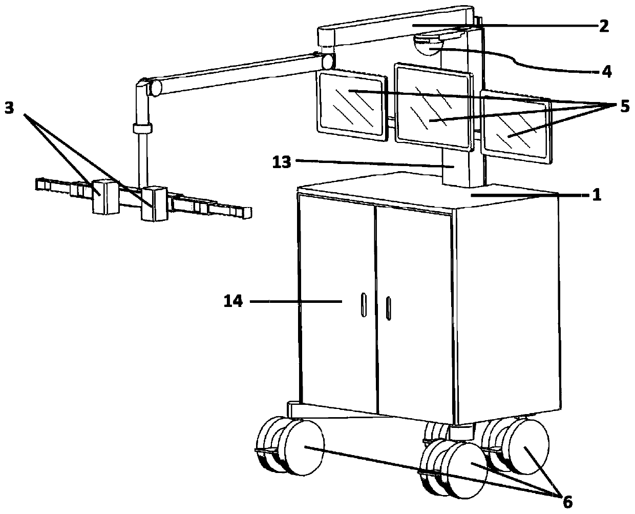
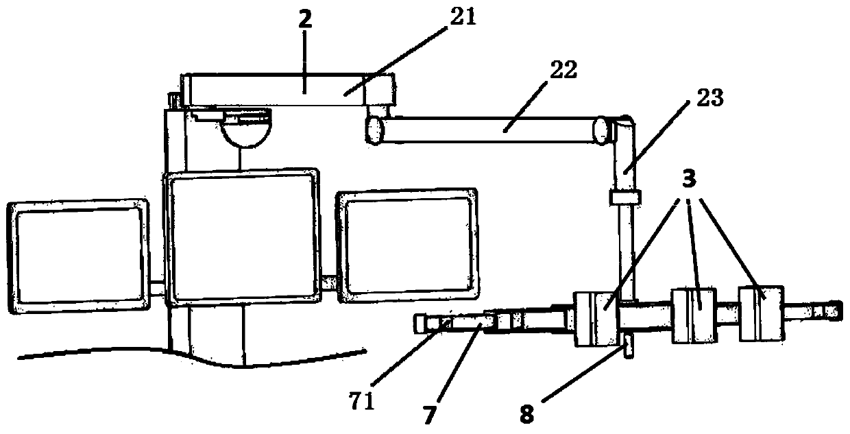
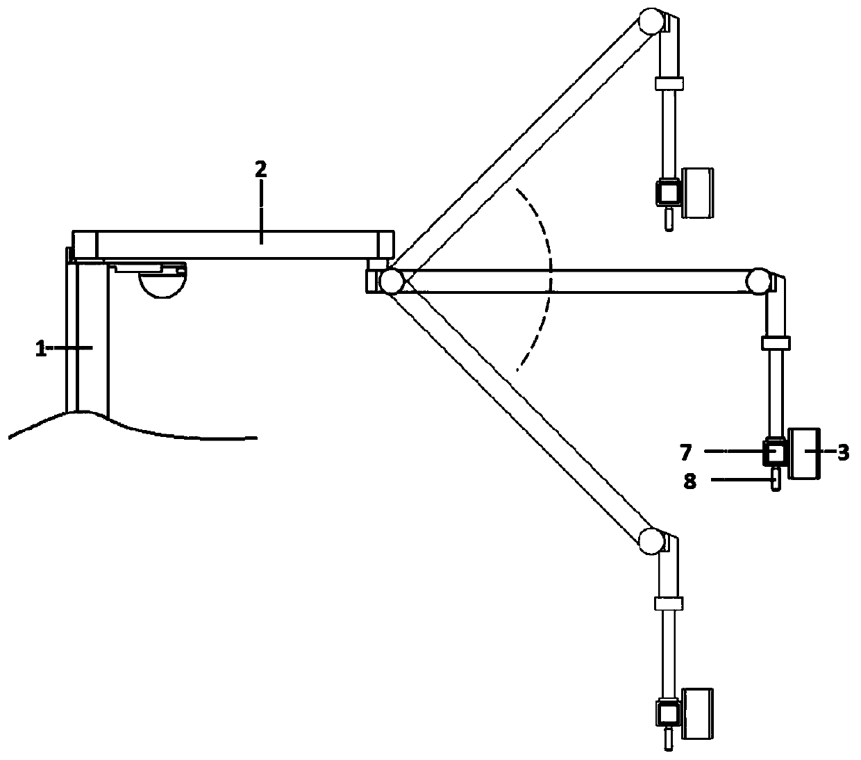
[0051] Such as figure 1 As shown, this embodiment provides a mobile robot exterior mirror system, which is mainly presented in the form of a mobile robot, including a robot carrier and an imaging system.

[0052] The robot carrier includes a robot arm 2 and a rectangular frame 1 . The base of the frame 1 is provided with four universal wheels 6 with a locking function; specifically, the base of the frame 1 is two main rods formed by intersecting each other at 90°, and the two main rods are connected to each other. The intersecting position is located at the rear section of the main pole, and the fixed column 13 of the robot arm 2 is vertically fixed on the intersection of the two main poles. The rear portion of the frame 1 is recessed, and the fixed column 13 That is, it is embedded in the depression; in addition, a wire groove is arranged in the fixed column 13 , and the top of the fixed column 13 is hingedly connected to the fixed end of the robot arm 2 .

[0053] The imag...

Embodiment 2

[0072] Such as Figure 17-18As shown, the similarities with Embodiment 1 will not be repeated. A pendant-type robot exterior mirror system provided in this embodiment is presented in the form of a pendant-type robot exterior mirror, including fixed installation on the ceiling The first carrier 11 and the second carrier 12, the first robot arm 111 and the second robot arm 121.

[0073] The first carrier 11 is used to carry the field camera 3, the scene camera 4 and the display 5, the second carrier 12 is used to carry the frame 1 storing the data processing host 142, the first carrier 11 and the The second carriers 12 are respectively suspended and fixed on the ceiling of the operating room. Further, the first carrier 11 is provided with two first robot arms 111 respectively corresponding to the display 5 and the camera; the second robot arm 121 provided also has the function of rotation adjustment, and the frame 1 is hoisted at the active end of the second robotic arm 121 . ...


PUM


Abstract

The invention discloses a novel robot outside mirror system. The system comprises an imaging system and a robot carrier; the imaging system comprises surgery field cameras, a display and a plurality of data processing hosts, and the surgery field cameras comprise at least two of a high definition camera, a 3D camera, an OCT camera, a laser confocal probe, an ultrasonic probe and an infrared camera; the robot carrier comprises a robot arm and a rack, and the robot arm comprises a fixed end and a movable end allowing position adjustment relative to the fixed end; and the surgery field cameras and the display are carried on the robot arm, and the data processing hosts are arranged on the rack. The system combines the robot structure with the imaging system, a doctor can control the whole operating room environment and the surgery process conveniently, accurately judge properties of focuses and make accurate treatment surgery plans in real time on sites, so that the surgery efficiency is greatly improved, and the surgical risk is reduced.

Description

technical field [0001] The invention belongs to the field of medical equipment, and in particular relates to a novel robot exterior mirror system. Background technique [0002] At present, in various large-scale clinical open operations, doctors generally rely on experience and various invasive medical diagnosis methods to diagnose patients' illnesses, which often bring pain and discomfort to patients during the diagnosis process, and at the same time, there are low detection accuracy. , Diagnosis efficiency is not high and other shortcomings. For example: [0003] In abdominal surgery, minimally invasive surgery, laparotomy or minimally invasive conversion to laparotomy are usually used. Minimally invasive surgery is usually performed laparoscopically, the incision is very small, the bleeding during the operation is less, the postoperative recovery is quicker, the psychological pressure of the patient is reduced, and the scar after recovery is relatively small. Therefore,...

Claims


Application Information

Patent Timeline
IPC IPC(8): A61B90/00H04N13/204A61B5/00A61B8/00H04N13/239H04N13/30
CPCA61B90/361A61B90/37A61B8/00A61B5/0066A61B2090/3612A61B2090/3735
Inventor 乔铁雷凌云高瑞乔景亮
Owner 广州乔铁医疗科技有限公司
Learn More