
Periodically arranged sparse array antenna and arrangement method thereof

A sparse array and periodic arrangement technology, which is applied to antenna arrays, antennas, and antenna arrays that are powered independently, can solve the problems of high production cost, large number of circuit units, and large number of antennas, so as to improve product consistency and reduce transmission and reception. Number of units, effect of reducing maintenance spare parts

Active Publication Date: 2019-07-12
成都中宇微芯科技有限公司
View PDF11 Cites 4 Cited by
  • Summary
  • Abstract
  • Description
  • Claims
  • Application Information

AI Technical Summary

Problems solved by technology

Under the same technical performance conditions, the number of antennas required is large, the number of circuit units is large, and the production cost is high
The second antenna layout method is an aperiodic structure, and the antenna spacing does not use a periodic structure, which is not convenient to use multiple identical modules to form a large-scale sparse array
[0006] In summary, the existing array antenna layout has no periodic structure, and it is not convenient to use multiple identical modules to form a large-scale sparse array; there is no sparse effect, and the number of antennas required under the same technical performance conditions is large, and the circuit Defects such as large number of units and high production costs

Method used


Image

  • Periodically arranged sparse array antenna and arrangement method thereof
  • Periodically arranged sparse array antenna and arrangement method thereof
  • Periodically arranged sparse array antenna and arrangement method thereof

Examples


Embodiment Construction

[0042] The principles and features of the present invention are described below in conjunction with the accompanying drawings, and the examples given are only used to explain the present invention, and are not intended to limit the scope of the present invention.

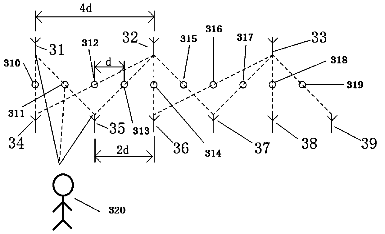
[0043]A periodically arranged sparse array antenna provided by an embodiment of the present invention includes:

[0044] S antenna periodic structures, each of which includes N1 transmitting antennas and N2 receiving antennas.

[0045] The N1 transmitting antennas are arranged in a first straight line, the N2 receiving antennas are arranged in a second straight line, the first straight line is parallel to the second straight line, and the first straight line is located in the first straight line above or below the two lines.

[0046] The S periodic antenna structures are arranged in sequence to form the array antenna, the array antenna includes M equivalent phase centers, and the M equivalent phase centers are arra...


PUM


Abstract

The invention relates to a periodically arranged sparse array antenna and an arrangement method thereof. The array antenna includes S antenna periodic structures, and each antenna periodic structure includes N1 transmitting antennas and N2 receiving antennas. The N1 transmitting antennas are arranged in a first straight line, the N2 receiving antennas are arranged in a second straight line, the first straight line is parallel to the second straight line, and the first straight line is located above or below the second straight line. The S antenna periodic structures are sequentially arranged into an array antenna, the array antenna comprises M equivalent phase centers, and the M equivalent phase centers are arranged in an equidistant straight line, wherein a midpoint between any one of thereceiving antennas and any one of the transmitting antennas in the array antenna is an equivalent phase center, and 1-S(N1+N2) / M is larger than 0. The use of the periodic structures facilitates the formation of reusable standard modules, the improvement of product consistency is facilitated, maintenance parts are reduced, the maintainability is improved, and the full life cost of a product is reduced.

Description

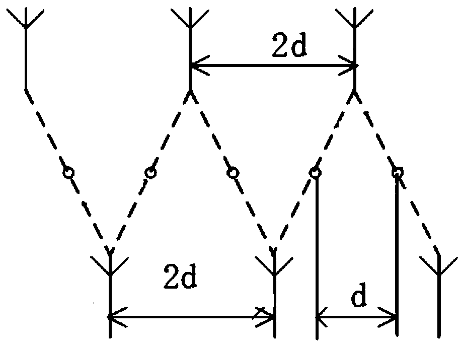
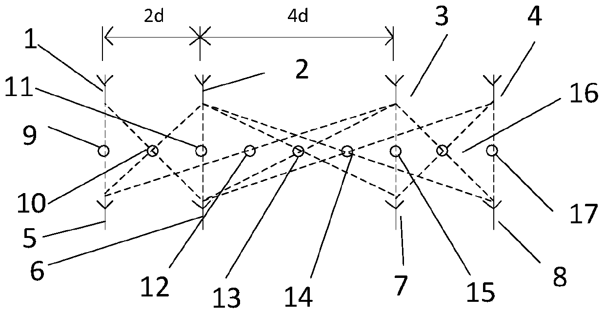
technical field [0001] The invention relates to the field of array antennas, in particular to a periodically arranged sparse array antenna and an arrangement method. Background technique [0002] The current array antenna layout is mainly in the following two forms: [0003] The first antenna layout method, such as figure 1 As shown, the transmitting antenna and the receiving antenna are uniformly arranged, and when the equivalent phase center is d, the distance between the transmitting antenna and the receiving antenna is 2d. The array composed of the first antenna layout has a spatial periodic structure every 2 antennas, and 2 phase centers are added for every 2 antennas, the sparse efficiency of the array antenna is (1-2 / 2)=0, and the array antenna has no sparse effect . [0004] The second antenna layout method, such as figure 2 As shown, when the distance between the equivalent phase centers is d, the distances between the transmitting antennas are 2d and 4d respec...

Claims


Application Information

Patent Timeline
IPC IPC(8): H01Q21/22H01Q21/00
CPCH01Q21/00H01Q21/0087H01Q21/22
Inventor 孟宪虎熊永忠齐胜翔
Owner 成都中宇微芯科技有限公司
Learn More