
Welding fixture of carrier roller bracket robot

A technology of robotic welding and idler support, applied in welding equipment, auxiliary welding equipment, welding/cutting auxiliary equipment, etc., can solve the problem of high technical requirements for personnel, weak commonality of welding fixtures, and only riveting and welding of specified products for a single fixture. and other problems, to achieve the effect of strong commonality, improved welding quality and product consistency

Pending Publication Date: 2018-06-22
TAIYUAN XIANGMING INTELLIGENT CONTROL TECH CO LTD
View PDF8 Cites 5 Cited by
  • Summary
  • Abstract
  • Description
  • Claims
  • Application Information

AI Technical Summary

Problems solved by technology

Using traditional welding fixtures requires at least two riveters and one welder. After the riveting is completed, the welder starts to weld. The technical requirements for personnel are high, and the welding quality and consistency are difficult to guarantee, and the welding effect is not good.
Moreover, the commonality of traditional welding fixtures is not strong, and a single fixture can only rivet and weld specified products

Method used


Image

  • Welding fixture of carrier roller bracket robot
  • Welding fixture of carrier roller bracket robot
  • Welding fixture of carrier roller bracket robot

Examples


Embodiment Construction

[0024] The robot welding jig of the idler bracket of the present invention will be further described in detail below in conjunction with the accompanying drawings.

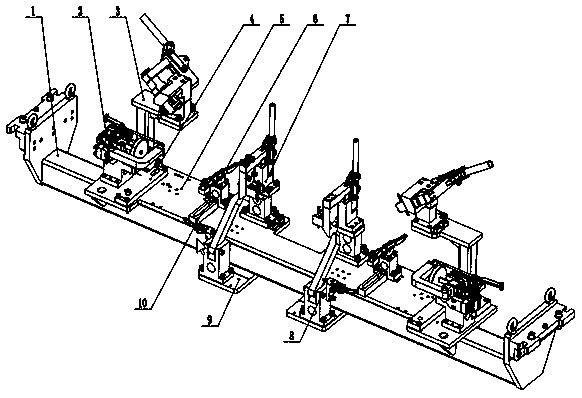
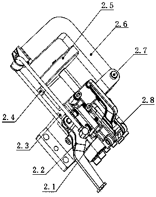
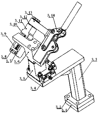
[0025] Such as figure 1 As shown, the robot welding fixture of the idler bracket of the present invention includes a common bottom beam, and the public bottom beam ( figure 2 There are side plates on both sides of the side plate, and lifting lugs are installed on the side plates to facilitate the hoisting and transportation of the entire equipment. There is a positioning groove on the outside of the mounting plate, and an L-shaped connecting plate for quick connection with the positioner is arranged in the positioning groove. The L-shaped connecting plate is provided with positioning pins for quick positioning, and the common bottom beam is provided with positioning mounting holes for replacing the quick-change platform.

[0026] The quick-change platform is installed on the front of the common bottom beam throu...


PUM


Abstract

The invention relates to the technical field of welding fixtures, in particular to a welding fixture of a carrier roller bracket robot. The welding fixture comprises a public bottom beam, a supportingpillar holding mechanism, a supporting pillar positioning mechanism, a base anchor positioning mechanism, a quick changing platform, a crossbeam clamping mechanism, a middle supporting pillar positioning mechanism, a medium supporting pillar clamping mechanism, a simple mounting plate and an L-shaped block. The quick changing platform is arranged on the upper surface of the public bottom beam. The supporting pillar holding mechanism and the supporting pillar positioning mechanism are symmetrically arranged on the left side and the right side of the end of the quick changing platform. The baseanchor positioning mechanism is fixed to the position, between the supporting pillar holding mechanism and the supporting pillar positioning mechanism, of the upper side of the quick changing platform. The middle supporting pillar positioning mechanism and the medium supporting pillar clamping mechanism are arranged in the middle of the quick changing platform. The middle of the quick changing platform is further provided with the L-shaped block and the crossbeam clamping mechanism. The L-shaped block is arranged under the crossbeam clamping mechanism. An installing hole is formed in the middle of the L-shaped block. The installing hole is a long and round countersunk head type groove. According to the welding fixture of the carrier roller bracket robot, the welding efficiency, the welding quality and the product consistency are improved significantly compared with a technology in the prior art.

Description

technical field [0001] The invention relates to the technical field of welding jigs, in particular to a welding jig for a roller support robot. Background technique [0002] Roller brackets are generally installed in belt conveyors and have the characteristics of many types and large quantities. The idler bracket can fix the idler and support the conveyor belt, and is an important supporting structure in the belt conveyor. The high-quality welded idler bracket not only fixes the idler, but also ensures the flexibility of the idler, and controls the radial runout and axial movement of the idler within a reasonable range; at the same time, it provides strong support to ensure that the idler and smooth operation of the conveyor belt. Although the structure of the roller bracket is simple, it is not easy to manufacture a high-quality roller bracket. The use of traditional welding fixtures requires at least two riveters and one welder. After the riveting is completed, the weld...

Claims


Application Information

Patent Timeline
Patent Type & Authority Applications(China)
IPC IPC(8): B23K37/04
CPCB23K37/0443B23K37/0461
Inventor 何磊常慧强张鑫
Owner TAIYUAN XIANGMING INTELLIGENT CONTROL TECH CO LTD
Learn More