
Cascaded fuzzy matching shaping system and shaping method for quasi-near-field focused beams

A technology of fuzzy matching and near-field focusing, applied in optics, optical components, instruments, etc., can solve the problems of destroying the corresponding relationship of the image plane and unable to effectively improve the near-field distribution.

Active Publication Date: 2021-01-05
HARBIN INST OF TECH
View PDF7 Cites 0 Cited by
  • Summary
  • Abstract
  • Description
  • Claims
  • Application Information

AI Technical Summary

Problems solved by technology

However, the light field of the beam section on the focusing path has characteristics between the near field and the far field, and the emphasizing effect destroys the correspondence between the image planes. The traditional beam space shaping method cannot effectively improve its near field distribution.

Method used


Image

  • Cascaded fuzzy matching shaping system and shaping method for quasi-near-field focused beams
  • Cascaded fuzzy matching shaping system and shaping method for quasi-near-field focused beams
  • Cascaded fuzzy matching shaping system and shaping method for quasi-near-field focused beams

Examples


specific Embodiment 1

[0042] according to figure 1 The schematic diagram shown in the figure builds an optical path diagram, and the system includes SLM1, a rear fundamental frequency optical amplification device 2, a frequency doubling system 3, a focusing lens 4, a sampling mirror 5, a CCD6 and a target target 7;

[0043] The base frequency light enters the incident end of the base frequency optical amplifying device 2 of the subsequent stage through the output end of the SLM1, enters the input end of the frequency doubling system 3 through the exit end of the base frequency optical amplifying device 2 of the latter stage, and passes through the output of the frequency doubling system end enters the incident end of the focusing lens 4, and the outgoing end of the focusing lens 4 converges the fundamental frequency light on the material surface of the target 7, and a sampling mirror 5 is arranged between the focusing lens 4 and the target 7, and the SLM1, the rear stage Base frequency optical ampl...

specific Embodiment 2

[0055] The invention of this example will be described in detail below in conjunction with the accompanying drawings.

[0056] The cascading fuzzy matching shaping algorithm instance of the quasi-near-field focused light beam is characterized in that the steps are as follows:

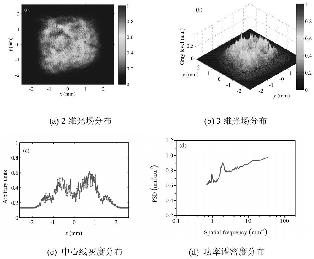
[0057] Step 1, according to figure 1 The schematic diagram shown in the figure builds an optical path diagram. The fundamental frequency beam sequentially passes through the SLM1, the subsequent fundamental frequency light amplification, the frequency doubling system 3 and the focusing lens 44 to converge on the target surface, and then samples the light field on the target surface through the sampling mirror 5 on the focusing path. , the consistency of the two optical paths must be strictly maintained in the experiment. The positioning aperture is loaded on the SLM1, and the positioning aperture is as follows figure 2 A circular diaphragm with a characteristic positioning hole is shown. Considering...


PUM


Abstract

The invention relates to a cascade fuzzy matching shaping system and a shaping method for a quasi-near-field focused beam. The establishment system of the invention comprises a SLM (1), a post-stage fundamental frequency optical amplifying device (2), a frequency multiplication system (3), a focusing lens (4), a sampling mirror (5), a CCD (6) and a target (7). The SLM (1) is loaded with a positioning aperture with feature positioning holes, an edge-softening initial square aperture, a shaping aperture of the fundamental frequency light, and a shaping aperture of the focused beam, and finally the output light field distribution after passing through the new aperture meets the set index. The SLM (1)-based laser shaping system has active beam shaping capability, and the closed-loop negative feedback system structure formed by the SLM (1)-based laser shaping system together with the measurement system and the calculation system is convenient and easy to operate, and has high contrast and high resolution.

Description

technical field [0001] The invention relates to the technical field of beam shaping, and relates to a cascade fuzzy matching shaping system and shaping method for quasi-near-field focused beams. Background technique [0002] The interaction between laser and matter, such as laser cladding, laser shock strengthening and other industrial processing fields, as well as the research fields of material damage and high-energy field physics under laser irradiation, in many cases requires both sufficient laser power density and hope The irradiation spot has a certain area, so the light beam is mostly irradiated on the surface of the material in the form of conoscopic light converged by the lens. Whether the irradiated surface in the conoscopic light has not yet reached the focal plane, whether its spot profile is regular, and whether the light intensity distribution is uniform, marks the quality of the actual laser irradiated field, and is an important condition parameter for the int...

Claims


Application Information

Patent Timeline
Patent Type & Authority Patents(China)
IPC IPC(8): G02B27/09
CPCG02B27/09
Inventor 李宇芯朱成禹远航
Owner HARBIN INST OF TECH
Learn More