
Spring making machine feed device

A tool feeding device and manufacturing machine technology, applied in the direction of manufacturing springs, static electricity, electrical components, etc. from wires, can solve problems that affect the normal processing of equipment, seal ring changes, and affect the production quality of equipment, etc.

Inactive Publication Date: 2020-05-12
佛山市功本弹簧五金制品有限公司
View PDF5 Cites 0 Cited by
  • Summary
  • Abstract
  • Description
  • Claims
  • Application Information

AI Technical Summary

Problems solved by technology

[0003] 1. However, under the long-term processing of the existing equipment, the sealing ring at the joint of the tool is easily heated and slightly deformed, causing a gap at the joint of the originally sealed tool. Under the reciprocating advancement of the tool, it is easy to lubricate the inside The liquid is squeezed out from the gap, flows down along the tool, and drops on the spring processing position, which affects the normal processing of the equipment
[0004] 1. At the same time, under the long-term processing of the cutting tool of the existing equipment, static electricity is easily generated on the cutting tool due to friction, which causes the cutting tool to absorb the surrounding dust and iron filings falling from the wire when the cutting tool is processing, thereby pushing the wire when the cutting tool enters When it sticks to the wire, it will affect the production quality of the equipment

Method used


Image

  • Spring making machine feed device
  • Spring making machine feed device
  • Spring making machine feed device

Examples


Embodiment

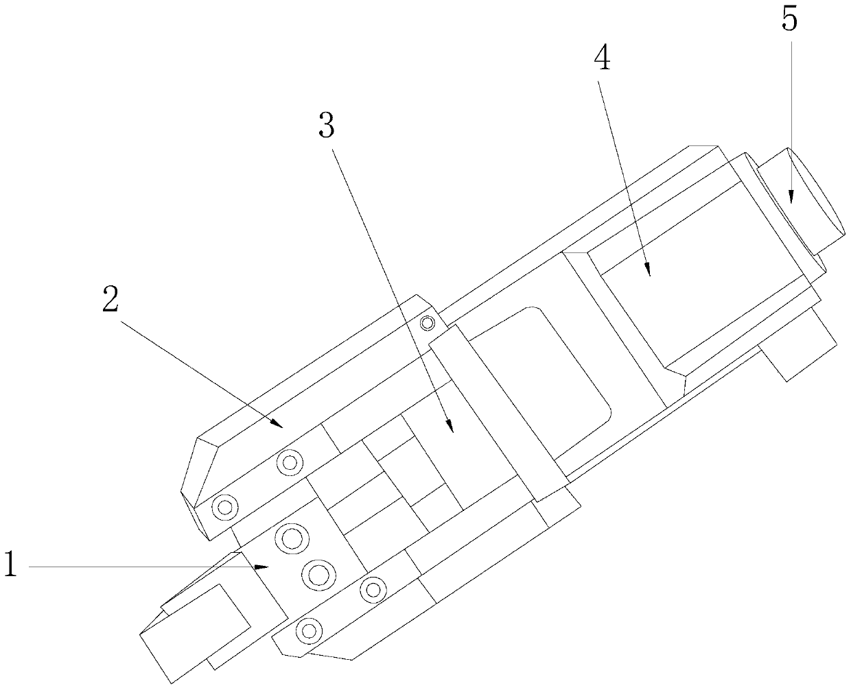
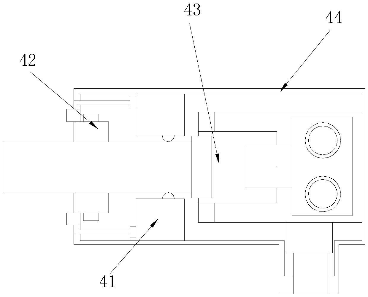
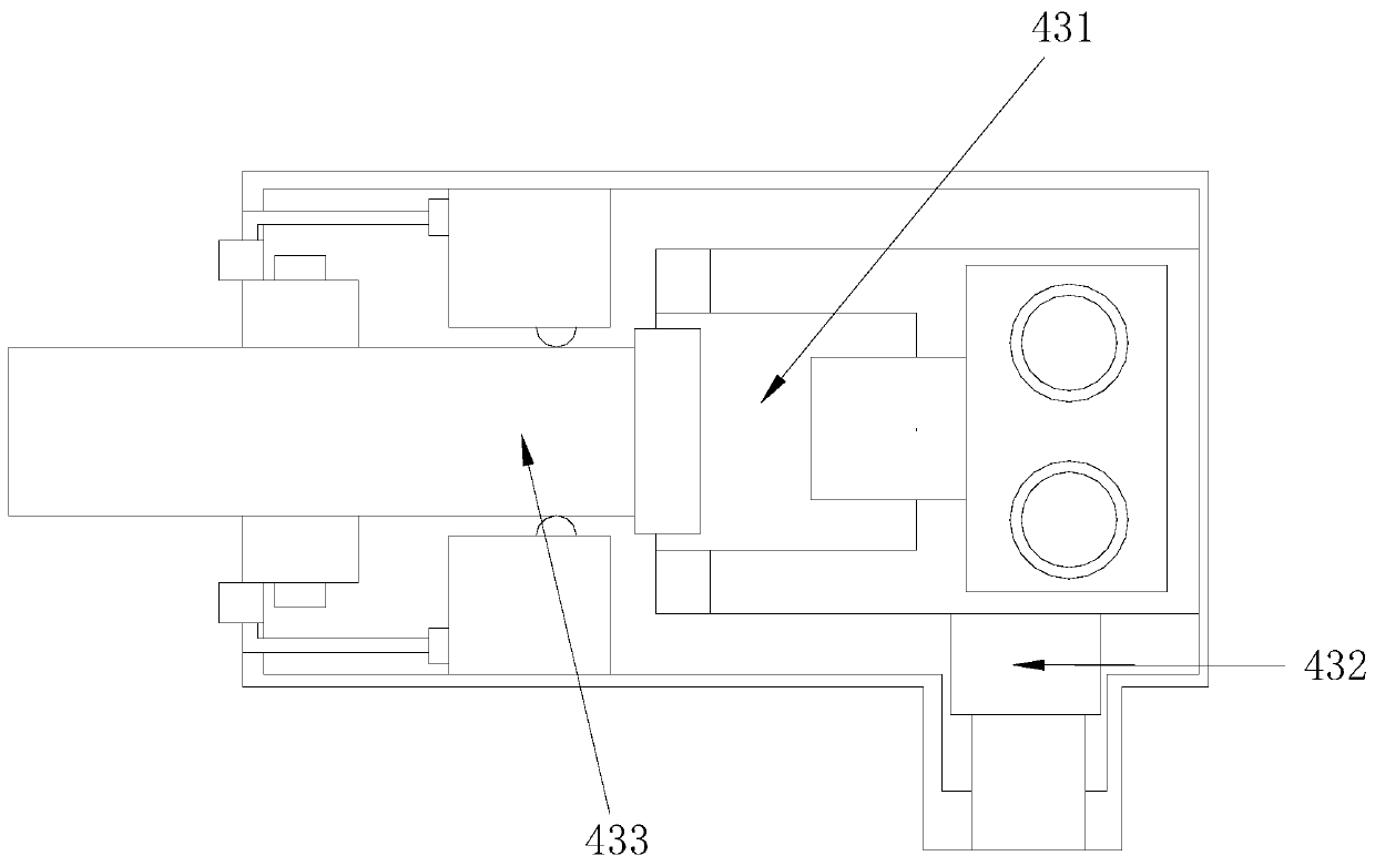
[0030] see Figure 1-Figure 7, the present invention provides a tool feeding device for a spring manufacturing machine. Its structure includes a tool connecting head 1, a side block 2, a push connecting block 3, a knife feeding mechanism 4, and a connecting block 5. The right end of the tool connecting head 1 is horizontally embedded in the push connecting block. In the middle of the left end of 3, the side blocks 2 are provided at the upper and lower ends of the tool connector 1, and the side blocks 2 are provided with two, which are respectively welded with the upper and lower ends of the push connecting block 3. The push connecting block 3 The right end of the feeding mechanism 4 is welded with the left end of the feeding mechanism 4. The right end of the feeding mechanism 4 and the left end of the connecting block 5 are integrated structures. 43. Housing 44, there are two static elimination components 41, which are respectively movably connected to the upper and lower ends...


PUM


Abstract

The invention discloses a feeder for a spring manufacturer. The feeder for the spring manufacturer structurally comprises a cutter connector, a side block, a pushing connection block, a feeding deviceand a connecting block. According to the feeder for the spring manufacturer provided by the invention, through the mutual combination of the components, when the feeder for the spring manufacturer isin use, the extrusion sealing performance of the connecting part of a feeding part of the equipment can be enhanced through a sealing enhancing mechanism; the occurrence of the phenomenon that a sealing ring at the cutter connecting part is easy to heat so as to be slightly deformed, a gap is produced at an original sealing cutter connecting part, and lubricating liquid in the equipment is pushedout through the gap, flows down along a cutter and drops on a spring processing site so as to influence the normal processing of the equipment is avoided; meanwhile, a pushing mechanism can drive a static elimination assembly to produce positive and negative ions onto the cutter during feeding so as to neutralize static electricity on the cutter; and the occurrence of the phenomenon that during the long-time processing of the cutter, the cutter is easy to produce the static electricity due to friction so as to adsorb surrounding dust and scrap iron fallen from wires, and the dust and the scrap iron are adhered onto the wires during processing so as to influence the production quality of the equipment is avoided.

Description

technical field [0001] The invention relates to the field of spring machine tool feeding devices, in particular to a spring manufacturing machine tool feeding device. Background technique [0002] The feeding device of the spring making machine is an indispensable part for making springs on the spring making machine. The cutting tool is pushed by the propulsion device to make it squeeze and push the wire to form a spring. [0003] 1. However, under the long-term processing of the existing equipment, the sealing ring at the joint of the tool is easily heated and slightly deformed, causing a gap at the joint of the originally sealed tool. Under the reciprocating advancement of the tool, it is easy to lubricate the inside The liquid is squeezed out from the gap, flows down along the tool, and drops on the spring processing position, which affects the normal processing of the equipment. [0004] 1. At the same time, under the long-term processing of the cutting tool of the exis...

Claims


Application Information

Patent Timeline
Patent Type & Authority Patents(China)
IPC IPC(8): B21F35/00H05F3/06
CPCB21F35/00H05F3/06
Inventor 郑丽凡
Owner 佛山市功本弹簧五金制品有限公司
Learn More