
Automatic taking out and burying equipment for special-shaped part injection molding

A technology for injection molding and special-shaped parts, which is applied in the direction of coating, etc., can solve the problems of low effect, affect the molding efficiency, and the lack of gripping effect of special-shaped material parts, so as to achieve the effect of ensuring stability

Pending Publication Date: 2019-07-09
HUIZHOU WEK PRECISION PART
View PDF0 Cites 1 Cited by
  • Summary
  • Abstract
  • Description
  • Claims
  • Application Information

AI Technical Summary

Problems solved by technology

The disadvantage of this kind of grasping is that it has strict requirements on the shape and structure of the object. The shape must have a large area, the plane is smooth and flat, the structure must be simple, and there must be enough suction cup adsorption positions; Gripping effect; therefore, we can only embed the material pieces one by one manually, but this method has certain risks; and the effect is also low, which affects the molding efficiency

Method used


Image

  • Automatic taking out and burying equipment for special-shaped part injection molding
  • Automatic taking out and burying equipment for special-shaped part injection molding
  • Automatic taking out and burying equipment for special-shaped part injection molding

Examples


Embodiment Construction

[0032] Below in conjunction with accompanying drawing and embodiment of description, specific embodiment of the present invention is described in further detail:

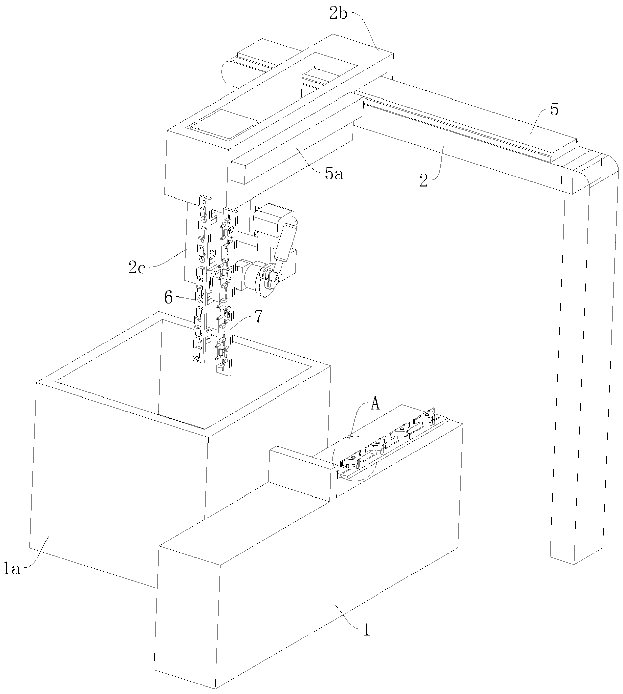
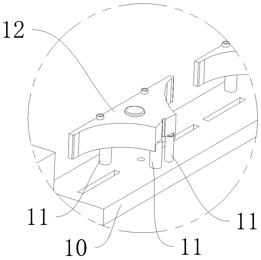
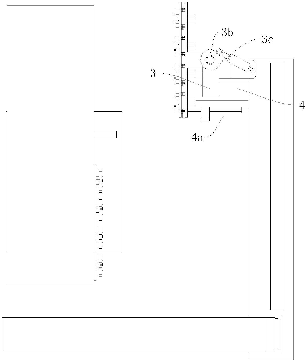
[0033] refer to Figure 1 to Figure 6 The shown automatic embedding equipment for injection molding of special-shaped parts includes a transfer table 1, an injection molding machine 1a, and a top beam frame 2 erected above the injection molding machine 1a. The transfer table 1 is set up around the injection molding machine 1a, and the embedding equipment It includes a turning mechanism, a lifting mechanism, and a first servo electric cylinder 5 arranged on the upper surface of the top beam frame 2. The top beam frame 2 is provided with a sliding beam 2b that is in right angle with it. Movably matched, and can reciprocate between the injection molding machine 1a and the turntable 1 through the first servo electric cylinder 5, the lifting mechanism can be set at the other end of the sliding beam 2b through the second ...


PUM


Abstract

The invention relates to the field of injection molding equipment, in particular to automatic taking out and burying equipment for special-shaped part injection molding. The automatic taking out and burying equipment for special-shaped part injection molding comprises a middle rotary table, an injection molding machine, a top beam frame arranged above the injection molding machine, a turnover mechanism, a lifting mechanism and a first servo electric cylinder arranged at the top of the top beam frame, wherein the middle rotary table is arranged at the periphery of the injection molding machine;a sliding beam matched with the top beam frame at a right angle is arranged on the top beam frame; the sliding beam can move back and forth between the injection molding machine and the middle rotarytable through the first servo electric cylinder; the lifting mechanism is movably arranged at the other end of the sliding beam through a second servo electric cylinder; the turnover mechanism is arranged on the output end of the lifting mechanism; the output end of the turnover mechanism is provided with a support beam; two sides of the support beam are respectively provided with a material taking plate and a buried plate, the material taking plate is movably matched with a support beam through a cylinder sliding table; and the bottoms of the material taking plate and the buried plate are respectively provided with a plurality of clamps and material suction clamps. According to the automatic taking out and burying equipment for special-shaped part injection molding, the safety risk caused by manual part taking and burying is avoided, and the production efficiency is improved.

Description

technical field [0001] The invention relates to the field of injection molding equipment, in particular to an automatic embedding equipment for injection molding of special-shaped parts. Background technique [0002] At present, in the field of injection molding, the grasping and embedding of material parts is carried out by adsorption, that is, a large suction cup is used to transport compressed air through the trachea to inhale and deflate, so that the suction cup forms a vacuum and thus absorbs the product. The disadvantage of this kind of grasping is that it has strict requirements on the shape and structure of the object. The shape must have a large area, the plane is smooth and flat, the structure must be simple, and there must be enough suction cup adsorption positions; The gripping effect; therefore, the material pieces can only be embedded one by one manually, but this method has certain risks; and the effect is also low, which affects the molding efficiency. Cont...

Claims


Application Information

Patent Timeline
Patent Type & Authority Applications(China)
IPC IPC(8): B29C45/14B29C45/42
CPCB29C45/14008B29C45/42
Inventor 陈剑周世风孙烨孙俊周乐旭
Owner HUIZHOU WEK PRECISION PART
Learn More