Antenna Direction Angle Optimization Method, Device, Equipment and Medium
A technology of antenna direction and optimal direction, applied in the field of communication, can solve the problems of output impact, large workload, incomplete test area, etc., to improve economic efficiency and reduce manpower and material resources.
- Summary
- Abstract
- Description
- Claims
- Application Information
AI Technical Summary
Problems solved by technology
Method used
Image


Examples
Embodiment 1
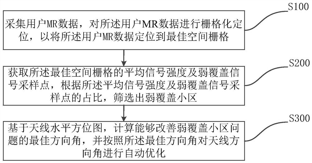
[0036] figure 1 A schematic flowchart of a method for optimizing an antenna orientation angle provided by Embodiment 1 of the present invention is shown. Such as figure 1 As shown, as a preferred embodiment, the method includes:
[0037] Step S100, collecting user MR data, and performing grid positioning on the user MR data, so as to locate the user MR data on an optimal spatial grid;
[0038] Preferably, as figure 2 As shown, the user MR data is rasterized and positioned to position the user MR data to an optimal spatial grid, specifically including:
[0039] Step S110, based on the user MR data, establish a spatial raster feature fingerprint library;
[0040] Step S120, using a longitude-latitude calibration algorithm to correct the fingerprint library;
[0041] Step S130, matching the user MR data with the feature vectors in the fingerprint library, and assigning the user MR data to an optimal spatial grid that can be matched.
[0042] Further preferably, step S110 s...
Embodiment 2
[0109] Corresponding to Embodiment 1 of the present invention, Figure 8 It shows a schematic structural diagram of an antenna orientation angle optimization device provided by Embodiment 2 of the present invention. The device includes: a data collection and positioning module 201 , a weak coverage cell screening module 202 , and an antenna orientation angle optimization module 204 .
[0110] The data collection and positioning module 201 is configured to collect user MR data, and perform grid positioning on the user MR data, so as to locate the user MR data on an optimal spatial grid.
[0111] Weak coverage cell screening module 202, configured to obtain the average signal strength and weak coverage signal sampling points of the optimal spatial grid, and filter out Weak coverage cells.
[0112] The antenna orientation angle optimization module 204 is configured to calculate an optimal orientation angle that can improve the problem of weakly covered cells based on the antenna...
Embodiment 3
[0115] Corresponding to Embodiment 1 of the present invention, Figure 9 It shows a schematic structural diagram of a computer device provided by Embodiment 3 of the present invention, and the device may include a processor 301 and a memory 302 storing computer program instructions.
[0116] Specifically, the above-mentioned processor 301 may include a central processing unit (CPU), or an application specific integrated circuit (Application Specific Integrated Circuit, ASIC), or may be configured to implement one or more integrated circuits in the embodiments of the present invention.
[0117] Memory 302 may include mass storage for data or instructions. By way of example and not limitation, the memory 302 may include a hard disk drive (Hard Disk Drive, HDD), a floppy disk drive, a flash memory, an optical disk, a magneto-optical disk, a magnetic tape, or a Universal Serial Bus (Universal Serial Bus, USB) drive or two or more Combinations of multiple of the above. Storage 30...
PUM
 Abstract
Description
Claims
Application Information
 - R&D
- Intellectual Property
- Life Sciences
- Materials
- Tech Scout
- Unparalleled Data Quality
- Higher Quality Content
- 60% Fewer Hallucinations
Browse by: Latest US Patents, China's latest patents, Technical Efficacy Thesaurus, Application Domain, Technology Topic, Popular Technical Reports.
© 2025 PatSnap. All rights reserved.Legal|Privacy policy|Modern Slavery Act Transparency Statement|Sitemap|About US| Contact US: help@patsnap.com