Electro-hydraulic control system, method and device

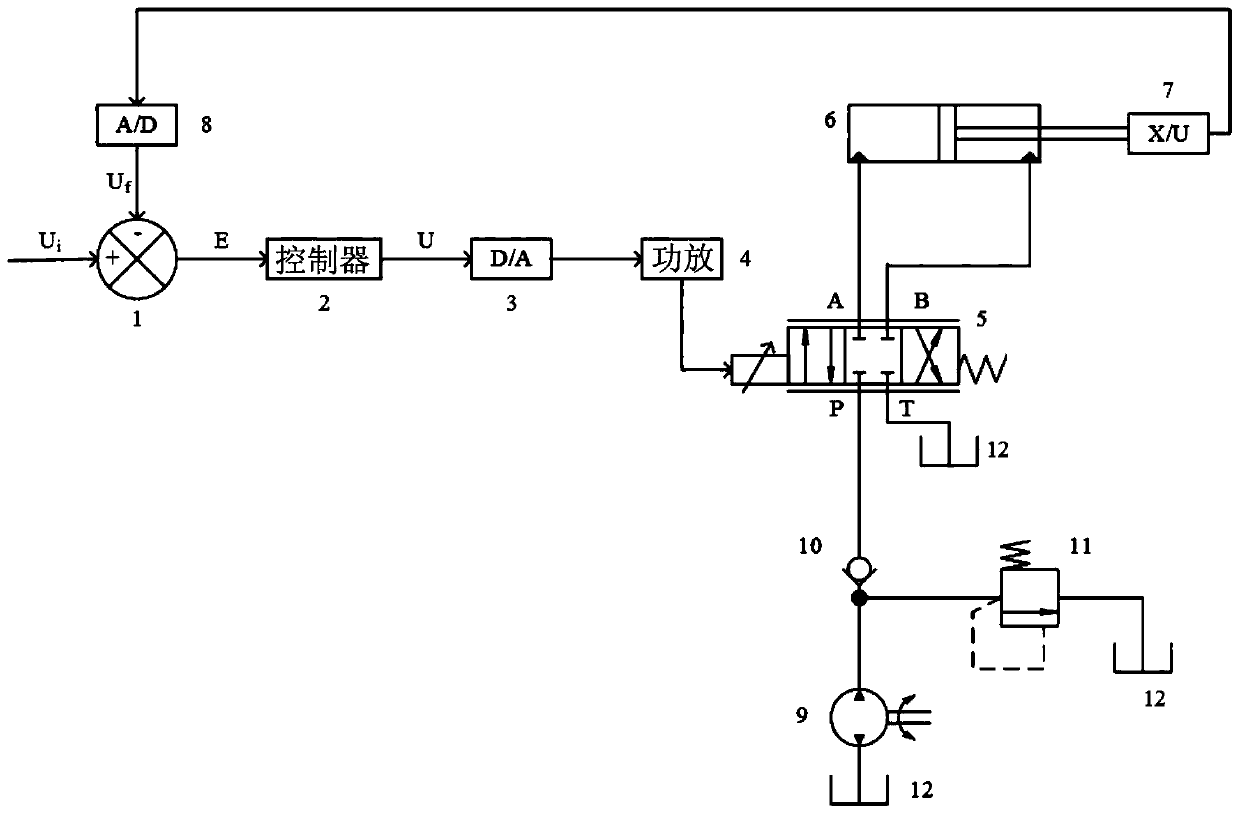
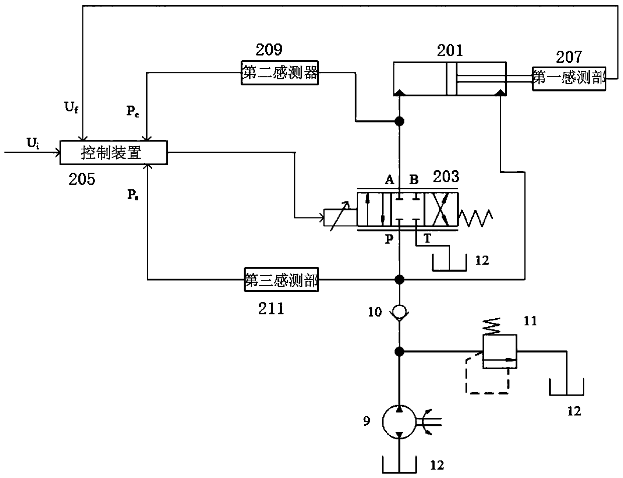
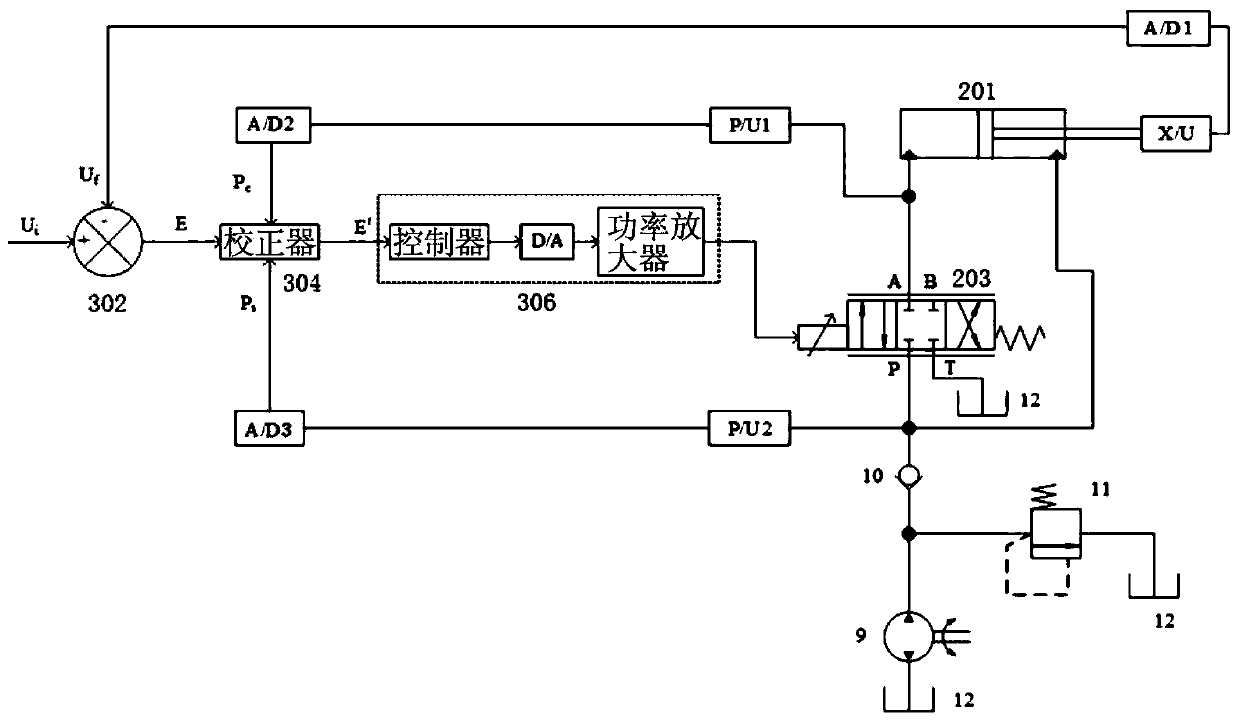
An electro-hydraulic control system and electro-hydraulic control technology are applied in fluid pressure actuation devices, fluid pressure actuation system components, servo meter circuits, etc., and can solve the displacement error detected by the displacement sensor 7, large displacement response fluctuations, Unable to accurately realize the pitch change of wind turbines and other issues, to achieve the effect of reducing displacement deviation, improving correction accuracy, and reducing influencing factors

Active Publication Date: 2020-05-12
BEIJING GOLDWIND SCI & CREATION WINDPOWER EQUIP CO LTD
View PDF8 Cites 0 Cited by
  • Summary
  • Abstract
  • Description
  • Claims
  • Application Information

AI Technical Summary

Problems solved by technology

[0004] However, during the working process of the hydraulic cylinder 6, the external load will cause interference force on the piston rod, so that there is a deviation or error in the displacement detected by the displacement sensor 7, that is, there is a large fluctuation in the displacement response under the action of the external load interference force, resulting in the entire The electro-hydraulic control system is not rigid enough, and the external load cannot move accurately
[0005] For example, when the electro-hydraulic proportional valve is used to change the pitch of a wind turbine, since the external load is the blade, the wind changes randomly during the working process of the wind turbine, and the changing wind load will cause a large and variable change in the blade. The interference load force caused by the displacement sensor 7 has a large error in the displacement, and finally the pitch of the wind turbine cannot be accurately realized.

Method used


Image

  • Electro-hydraulic control system, method and device
  • Electro-hydraulic control system, method and device
  • Electro-hydraulic control system, method and device

Examples


Embodiment Construction

[0029] The present invention may have various modifications and various embodiments, and it should be understood that the present invention is not limited to these embodiments, but includes all modifications, equivalents and replacements within the spirit and scope of the present invention.

[0030] In the present invention, expressions including ordinal numbers such as "first" and "second" can modify various elements. However, these elements are not limited by such expressions. A first element could be termed a second element, and, similarly, a second element could be termed a first element, without departing from the scope of example embodiments of the present invention.

[0031] The terms used in the example embodiments of the present invention are for describing specific embodiments only, and are not intended to limit the example embodiments. As used herein, the singular forms are intended to include the plural forms as well, unless the context clearly dictates otherwise....


PUM


Abstract

The invention provides an electro-hydraulic control system, method and device. The electro-hydraulic control system can comprise a hydraulic cylinder, an electro-hydraulic proportional valve and the control device, wherein the hydraulic cylinder controls moving of the load, the electro-hydraulic proportional valve controls the direction and the flow quantity of hydraulic oil inside an oil box flowing into the hydraulic cylinder according to control signals used for controlling a valve core of the electro-hydraulic proportional valve to move, and the control device calculates a deviation valuebetween a displacement target value and an actual displacement value of the hydraulic cylinder, corrects the deviation value according to the pressure relationship between a first pressure value of arodless cavity of the hydraulic cylinder and a second pressure value of an oil inlet of the electro-hydraulic proportional valve and generates the control signals based on the corrected deviation value. According to the electro-hydraulic control system, method and device, by means of real-time correction on deviation signals, the correction accuracy is improved, displacement deviation caused by load disturbance force is reduced, and the system stiffness is increased.

Description

technical field [0001] The following description relates to an electro-hydraulic control system, method and device. Background technique [0002] The electro-hydraulic proportional valve is a valve that continuously and proportionally controls the flow direction, flow and pressure of the hydraulic system according to the input electrical signal. [0003] figure 1 An electro-hydraulic control system is shown. The displacement sensor 7 installed on the hydraulic cylinder 6 detects the displacement of the piston rod of the hydraulic cylinder 6 in real time, and the displacement feedback signal detected and output by the displacement sensor 7 is converted into U by the analog-to-digital converter 8. f , set the displacement signal U i and the displacement feedback signal U of the hydraulic cylinder 6 f Comparator 1 performs difference calculation to obtain deviation signal E, and the deviation signal E obtains the drive signal U of the electro-hydraulic proportional valve af...

Claims


Application Information

Patent Timeline
Patent Type & Authority Patents(China)
IPC IPC(8): F15B13/04F15B13/16F15B21/02
CPCF15B13/04F15B13/16F15B21/02F15B2211/6306F15B2211/6336F15B2211/6656
Inventor 刘博
Owner BEIJING GOLDWIND SCI & CREATION WINDPOWER EQUIP CO LTD
Why Eureka
Try Eureka