
Novel high-frequency structure of double-confocal waveguide gyro traveling wave tube

A technology of waveguide structure and high-frequency structure, which is applied in the field of millimeter wave and terahertz devices and microwave, can solve the problems of uneven distribution of transverse field of confocal waveguide, low efficiency of confocal waveguide gyrotraveling wave tube, interaction between electron and high frequency field Insufficient effect and other problems, to achieve good mode selection characteristics, uniform distribution of transverse field, and improve work efficiency

Inactive Publication Date: 2019-06-28
UNIV OF ELECTRONICS SCI & TECH OF CHINA
View PDF0 Cites 6 Cited by
  • Summary
  • Abstract
  • Description
  • Claims
  • Application Information

AI Technical Summary

Problems solved by technology

[0005] Due to the uneven distribution of the transverse field of the confocal waveguide, the interaction between some electrons and the high-frequency field is insufficient, so the efficiency of the confocal waveguide gyrotraveling wave tube is lower than that of the circular waveguide gyrotraveling wave tube

Method used


Image

  • Novel high-frequency structure of double-confocal waveguide gyro traveling wave tube
  • Novel high-frequency structure of double-confocal waveguide gyro traveling wave tube
  • Novel high-frequency structure of double-confocal waveguide gyro traveling wave tube

Examples


Embodiment Construction

[0015] The present invention is described in detail below through an embodiment that works near 140GHz. It is necessary to point out that this embodiment is only used to further illustrate the present invention, and cannot be interpreted as a limitation to the protection of the present invention. Those skilled in the art Some non-essential improvements and adjustments can be made based on the content of the present invention above.

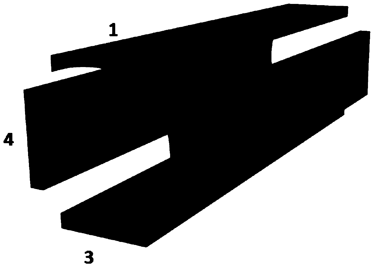
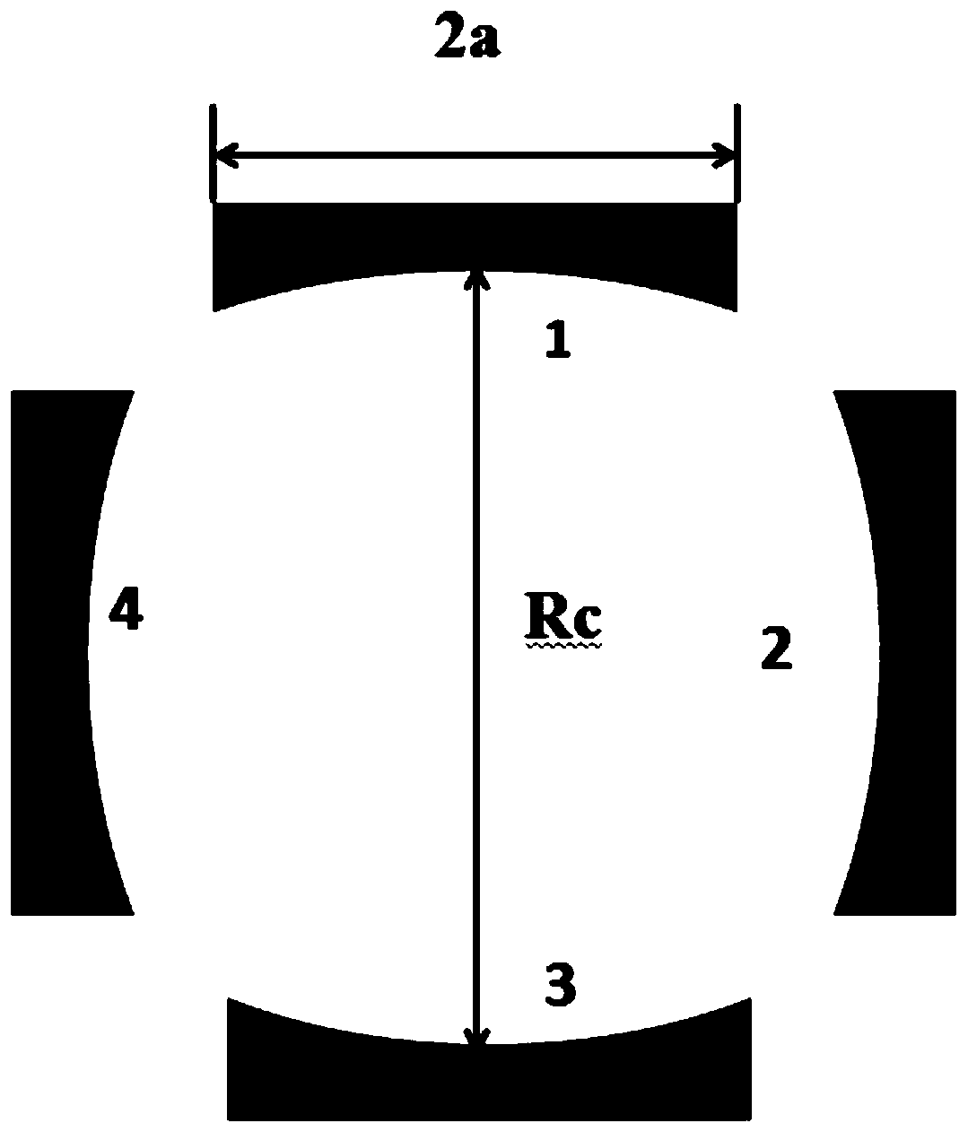
[0016] attached figure 1 And attached figure 2 There are two key parameters in the biconfocal waveguide structure diagram: mirror spacing Rc and mirror width 2a.

[0017] The value of the mirror distance Rc depends on the working frequency and working mode of the gyrotron TWT. For example, when working at 140GHz, the working mode is superposition mode HE 06 For the convoluted traveling wave tube of the mode, Rc can take a value of 6.9mm.

[0018] The value of the mirror width 2a determines the size of the gap at the side opening of the biconf...


PUM


Abstract

The invention relates to a novel high-frequency structure for a gyro traveling wave tube, which is called as a double-confocal waveguide. The structure is characterized in that the structure consistsof two groups of single confocal waveguides, wherein each group of single confocal waveguides consists of confocal mirrors, the curvature radiuses of which are equal to the distance between the mirrors. Therefore, the double-confocal waveguides are totally composed of four same and symmetrically distributed confocal mirrors. The double-confocal waveguides have sparse mode density and good mode selection characteristics, so that the high-order mode work of the gyro traveling wave tube is realized, and the working frequency of the gyro traveling wave tube is expanded to be above the W wave band(94 GHz). Compared with the traditional single confocal waveguide, the novel double confocal waveguides have the advantage that the beam-wave interaction efficiency of the gyro traveling wave tube isobviously improved.

Description

technical field [0001] The invention belongs to the technical field of microwave, millimeter wave and terahertz devices, and specifically relates to a high-frequency structure of a double-confocal waveguide gyrotraveling wave tube, which can be applied to gyrotraveling wave tubes in the millimeter wave and terahertz bands. Background technique [0002] As a microwave electric vacuum device based on the electron cyclotron maser mechanism, the Gyro-TWT amplifier has the characteristics of broadband, high power, and high efficiency in the millimeter-wave and even terahertz frequency bands. It has broad application prospects in modern high-performance radar, long-distance communication technology, electronic countermeasures and other fields [0003] The gyrotron TWT uses a smooth waveguide as its interaction structure, which theoretically has a wider bandwidth and higher efficiency than other amplifiers based on the electronic gyromaser mechanism. However, the GWT with a smooth...

Claims


Application Information

Patent Timeline
Patent Type & Authority Applications(China)
IPC IPC(8): H01J23/36H01J25/34
Inventor 刘頔威张晨王维宋韬
Owner UNIV OF ELECTRONICS SCI & TECH OF CHINA
Learn More