
Solid scattered material discharging controlling device

A control device and bulk material technology, applied in packaging, loading/unloading, transportation and packaging, etc., can solve problems such as fast flow or stagnant flow, prone to rapid flow and stagnant flow, material flow deviation, and setbacks , to achieve the effect of easy maintenance or replacement, low risk of clogging and high control precision

Inactive Publication Date: 2019-06-28
XI AN JIAOTONG UNIV
View PDF6 Cites 1 Cited by
  • Summary
  • Abstract
  • Description
  • Claims
  • Application Information

AI Technical Summary

Problems solved by technology

Butterfly valves and gate valves control the flow of bulk materials through the opening of the valves. Due to their structural characteristics, the control accuracy of the flow rate of bulk materials in the above-mentioned discharge device is poor and the range is narrow. , frustration, local fast flow or stagnant flow
The star-shaped discharge valve and the screw discharger discharge the bulk material through the continuous rotation of the star-shaped blade and the spiral blade. The flow state of the bulk material on the upper part of the discharge device is affected by the star-shaped blade interval and pitch. When the blade interval and pitch are smaller than the inlet , prone to material flow deflection, local fast flow and stagnation flow, it is difficult to realize the approximate overall and continuous flow of bulk material above the discharge device, when the blade interval and pitch are larger than the inlet, the volume of the discharge device is large , the bulk flow rate control accuracy is poor

Method used


Image

  • Solid scattered material discharging controlling device
  • Solid scattered material discharging controlling device
  • Solid scattered material discharging controlling device

Examples


Embodiment Construction

[0032] The technical solutions in the embodiments of the present invention will be clearly and completely described below in conjunction with the accompanying drawings in the embodiments of the present invention. Obviously, the described embodiments are only part of the embodiments of the present invention, not all embodiments. Based on the embodiments of the present invention, all other embodiments obtained by those skilled in the art without making creative efforts belong to the protection scope of the present invention.

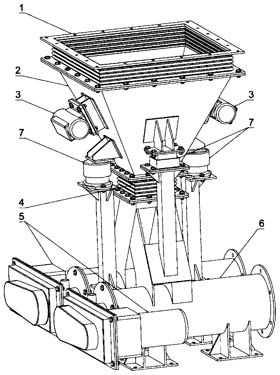
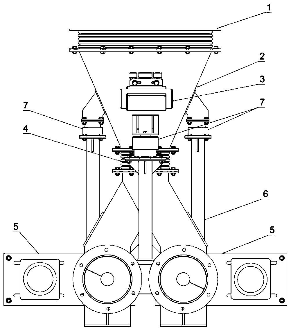
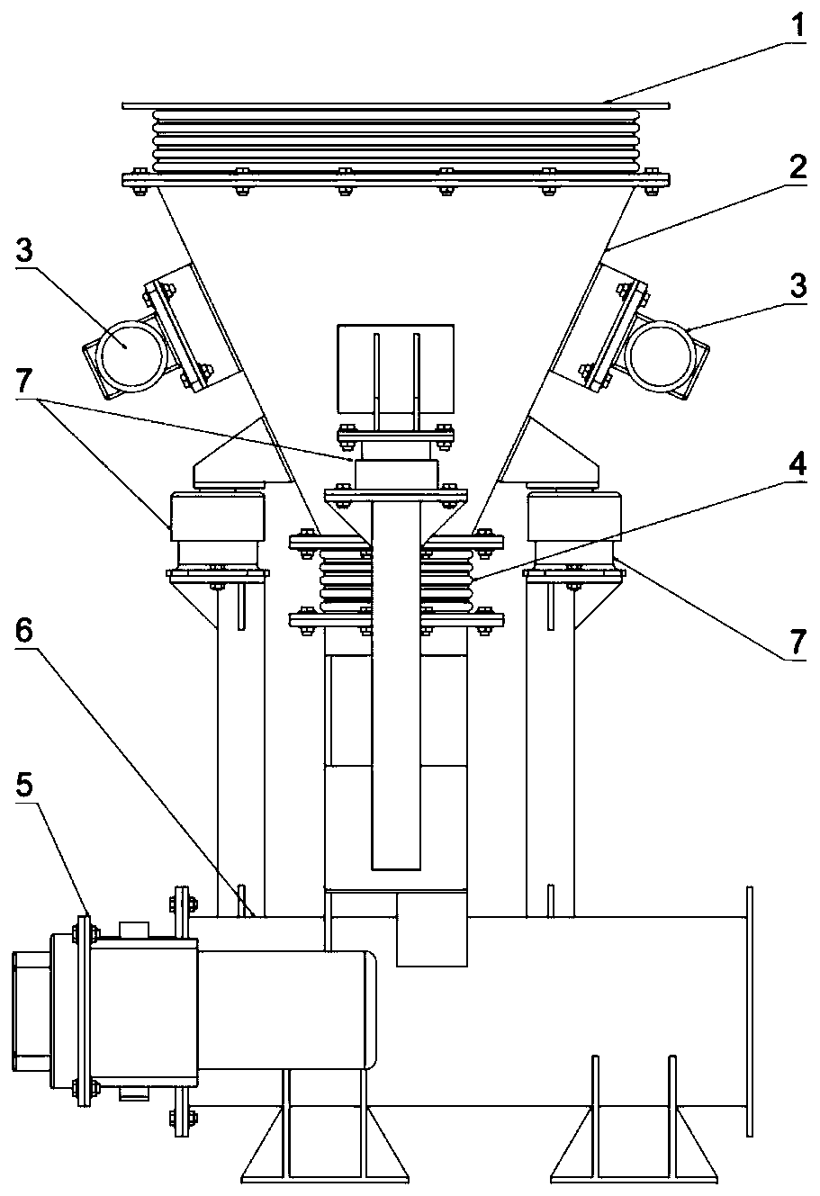
[0033] Depend on Figure 1-3 It can be seen that a solid bulk material discharge control device of the present invention is mainly composed of a hopper with a flexible connection flange 1, a hopper with a 2, a vibration generator 3, a flexible connection flange 4, a bulk material drive device 5, and a casing for a discharge control device. 6 and shock absorber 7 form. The inside of the feeding hopper 2 is provided with a conical shroud 2-5, the top of the...


PUM


Abstract

The invention relates to a solid scattered material discharging controlling device. The device comprises a feeding hopper, a scattered material driving device and a discharging controlling device housing. The feeding hopper is externally provided with a vibrator, and a conical guiding hood is arranged in the feeding hopper. The discharging controlling device housing is mainly composed of a scattered material conveying pipe and a scattered material feeding passage which is arranged on the top of the housing, the scattered material conveying pipe is composed of two circular pipes with the same diameter, and the scattered feeding passage is composed of two rectangular pipes. The feeding hopper and the scattered material feeding passage are connected and fixed by a soft connecting flange and ashock-absorbing device. The scattered material driving device is provided with spiral blades and a driving motor, and two groups of the spiral blades are fixed in the scattered material conveying pipe. The device has the advantages that the scattered material in the upper portion of the discharging device can flow approximately as a whole without obvious material flowing deflecting, blocking andnonuniform speed distribution, the device can be operated at a higher temperature, and therefore the continuous and stable movement of the scattered material at a lower flow rate is achieved.

Description

technical field [0001] The invention relates to a solid bulk material discharge control device, which is mainly aimed at controlling the flow of bulk material within a certain particle size range, especially powder, and is mainly used for high-temperature bulk material heat exchangers. The device can realize bulk material at a lower temperature Continuous and stable motion at flow rates. Background technique [0002] In the production process of metallurgy, building materials and other industries, a large amount of high-temperature bulk or powdery bulk materials will be produced. The cooling methods of these bulk materials are mainly divided into direct heat exchange and indirect heat exchange. The heat surface is isolated to avoid problems such as dust removal, bulk material or heat exchange medium pollution, and the application prospect is broader. The indirect heat exchange methods mainly include tube-row heat exchangers and plate heat exchangers. The bulk material fills...

Claims


Application Information

Patent Timeline
Patent Type & Authority Applications(China)
IPC IPC(8): B65G65/46B65G65/00B65G33/24B65D88/66B65D90/00
Inventor 杨剑田兴郭志罡王秋旺
Owner XI AN JIAOTONG UNIV
Learn More