A palm-fixed stent for arterial puncture
A fixed stent and arterial puncture technology, applied in the mechanical field, can solve the problems of stabbing patients, puncture failure, etc., and achieve the effect that the height cannot be adjusted and the arm can be avoided.
- Summary
- Abstract
- Description
- Claims
- Application Information
AI Technical Summary
Problems solved by technology
Method used
Image

Examples
Embodiment 1
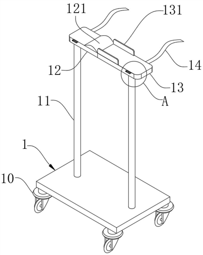
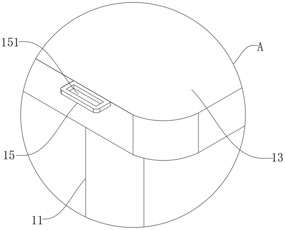
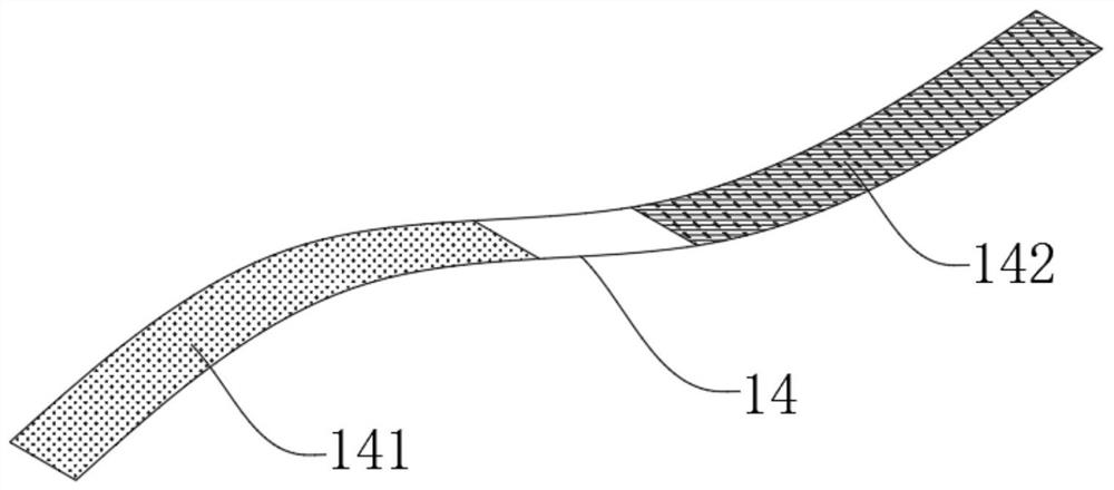
[0036] As the first embodiment of the present invention, a kind of arterial puncture uses palm to fix stent, as Figure 1 to Figure 3 As shown, including the base plate 1, the bottom surface of the base plate 1 is provided with several universal wheels 10 arranged in a matrix, and the upper surface of the base plate 1 is closely welded with two mutually symmetrical and vertically distributed support rods 11, one of which The top of the support rod 11 is provided with a first support frame 12 distributed horizontally, an arc pad 121 is provided on the upper surface of one end of the first support frame 12, and the top of the other support rod 11 is provided with a horizontally distributed The second bracing frame 13, the first bracing frame 12 and the second bracing frame 13 are all provided with an elastic band 14, the back side of the elastic band 14 is provided with a hair Velcro 141, and the back side of the elastic band 14 is also provided with a thorny Velcro 142, bonding...
Embodiment 2
[0044] As the second embodiment of the present invention, in order to facilitate the use of patients with different arm lengths, the inventors made improvements to the first support frame 12 and the second support frame 13, as a preferred embodiment, such as Figure 4 to Figure 8 As shown, the second support frame 13 is provided with a storage tank 2 connected to the outside world, the top wall and the bottom wall of the storage tank 2 are provided with a first sliding slot 20, and the front side wall of the storage tank 2 is also provided with There is a first threaded hole 21 communicating with the outside world, the first threaded hole 21 is internally threaded with a screw 22, the end of the screw 22 is provided with a turntable 23, and the position facing the receiving groove 2 on the first support frame 12 is provided with a fixed block 3. The fixed block 3 is located in the storage tank 2 and is slidingly connected with the storage tank 2. On the front side of the fixed ...
Embodiment 3
[0052] As a third embodiment of the present invention, in order to facilitate the adjustment of the height of the first support frame 12 and the second support frame 13, the inventors made improvements to the bottom plate 1 and the support rod 11, as a preferred embodiment, such as Figure 9 to Figure 11 As shown, the upper surface of the base plate 1 facing the position of the support rod 11 is also tightly welded with a vertically distributed screw sleeve 6, and the screw sleeve 6 is provided with a third threaded hole 60 communicating with the outside world. The third threaded hole 60 internal threads are connected with a screw rod 61, the screw rod 61 is tightly welded with a fixed column 62, and the top of the screw rod 61 is also tightly welded with a limit plate 63, and the two screw rods 61 are connected by a transmission belt 64, and the transmission belt 64 is located between the fixed column 62 and the limit plate. Between the disks 63 , bearings 65 are tightly welde...
PUM
 Abstract
Description
Claims
Application Information
 - R&D
- Intellectual Property
- Life Sciences
- Materials
- Tech Scout
- Unparalleled Data Quality
- Higher Quality Content
- 60% Fewer Hallucinations
Browse by: Latest US Patents, China's latest patents, Technical Efficacy Thesaurus, Application Domain, Technology Topic, Popular Technical Reports.
© 2025 PatSnap. All rights reserved.Legal|Privacy policy|Modern Slavery Act Transparency Statement|Sitemap|About US| Contact US: help@patsnap.com