Electronic device and control method thereof

A technology of electronic equipment and control methods, which is applied in the direction of electrical program control, sequence/logic controller program control, etc., can solve problems such as system shutdown, excessive instantaneous load of main power supply, and oscillation, so as to avoid oscillation and improve power supply. efficiency effect

Active Publication Date: 2017-11-28
LENOVO (BEIJING) LTD
View PDF7 Cites 0 Cited by
  • Summary
  • Abstract
  • Description
  • Claims
  • Application Information

AI Technical Summary

Problems solved by technology

However, since the sleep / working state switching of the two slave power supplies is carried out simultaneously when the conditions are met, when the two slave power supplies enter the sleep state at the same time, the load on the main power supply may be too large, and the system will re-enable the two slave power supplies. The power supply returns to the working state, and after the two slave power supplies return to the working state, the load of the main power supply is too small because the load is evenly distributed by the three power supplies, and the system will make the two slave power supplies enter the dormant state again, and so on, causing the power supply Oscillation of the working state, which leads to the instability of the whole power system and the instability of the efficiency of the power system
Even though the system didn't put two slave power supplies to sleep after the three power supplies shared the load evenly, the power supplies were still less efficient due to the small overload on each power supply distribution
Also, when both slaves go to sleep at the same time, the master may shut down the system due to momentary excessive load

Method used


Image

  • Electronic device and control method thereof
  • Electronic device and control method thereof
  • Electronic device and control method thereof

Examples


Embodiment Construction

[0015] In order to make the objects, technical solutions and advantages of the present invention more apparent, exemplary embodiments according to the present invention will be described in detail below with reference to the accompanying drawings. Apparently, the described embodiments are only some embodiments of the present invention, rather than all embodiments of the present invention, and it should be understood that the present invention is not limited by the exemplary embodiments described herein. Based on the embodiments described herein, all other embodiments obtained by those skilled in the art without creative effort shall fall within the protection scope of the present invention. In this specification and the drawings, substantially the same elements and functions will be denoted by the same reference numerals, and repeated descriptions of these elements and functions will be omitted. Also, descriptions of functions and constructions that are well known in the art m...


PUM


Abstract

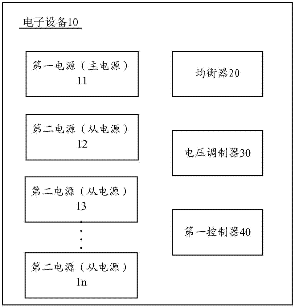
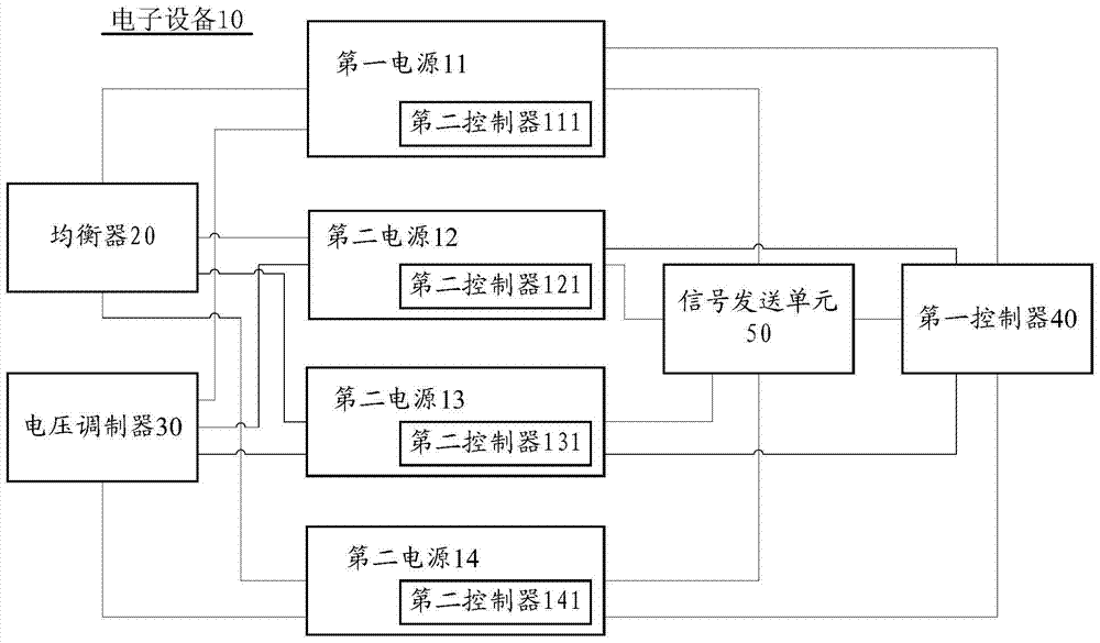
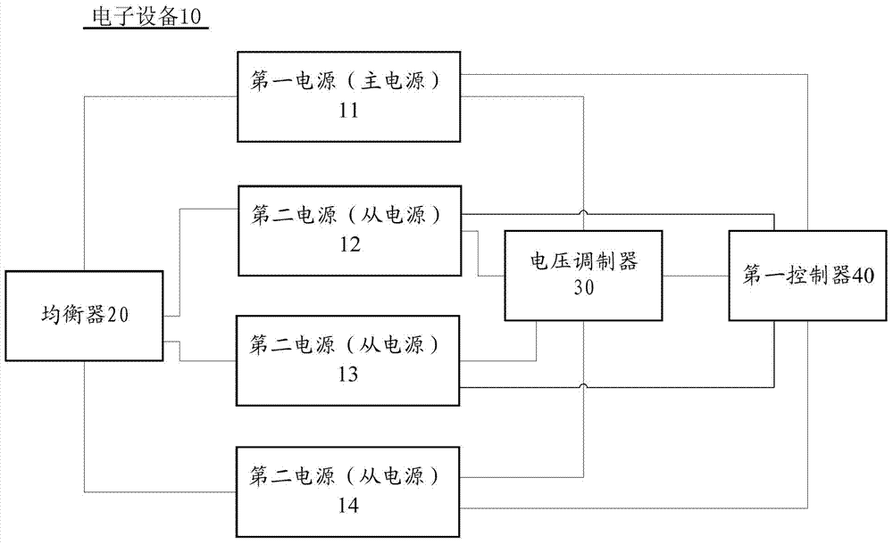
The invention discloses electronic equipment which comprises the components of a first controller; a first power supply and at least two second power supplies, wherein each power supply can be switched between an awakening state and a dormant state, each second power supply has a respective priority, and furthermore each power supply has a respective dormancy threshold voltage and an awakening threshold voltage; an equalizer which equalizes the output current of each of the first power supply and the second power supplies to a first current; and a voltage modulator which performs modulation according to the first current for generating a first voltage; wherein if the dormancy threshold voltages of multiple second power supplies in the second power supplies in the awakened state is higher than the first voltage, a first controller performs controlling according to the priority for making the multiple second power supplies into the dormant state; and if the awakening threshold voltages of each of the first power supply and the second power supplies in the awakened state is lower than the first voltage, the first controller performs controlling according to the priority for making the second power supplies in the dormant state enter the awakening state.

Description

technical field [0001] The invention relates to an electronic device and a control method thereof, in particular to an electronic device capable of improving power supply efficiency in a multi-power supply system and a control method thereof. Background technique [0002] In a server system powered by multiple power supplies, the efficiency of the power supplies usually varies with system power. Taking dual power supply as an example, the system usually sets one of the power supplies as the main power supply, and the other as the slave power supply. When the system is turned on, the main power supply is always in the working state to ensure the basic operation of the system. The system load can be switched between the active state and the sleep state, thereby optimizing the overall efficiency of the two power supplies. However, in the case where the server system is connected to more power supplies, the above-mentioned power supply and state switching mode of the master / sla...

Claims


Application Information

Patent Timeline
Patent Type & Authority Patents(China)
IPC IPC(8): G05B19/04
CPCG05B19/04
Inventor 周建军
Owner LENOVO (BEIJING) LTD
Why Eureka
Try Eureka