
Harvester waste heat drying system

A drying system and harvester technology, applied in the field of harvester drying system, can solve the problems of inconvenient manual exposure operation, increase energy consumption of dryer, reduce grain production efficiency, etc., and achieve stable drying temperature and structure Simple, easy-to-touch effect

Active Publication Date: 2019-06-21
青岛艾孚智能装备有限公司
View PDF8 Cites 8 Cited by
  • Summary
  • Abstract
  • Description
  • Claims
  • Application Information

AI Technical Summary

Problems solved by technology

However, after the traditional harvester harvests and collects, because there is no drying device, the relatively high value of free moisture and combined moisture carried by the grain itself has not been evaporated and lost. The time is short, so it is necessary to use special grain drying equipment to dry the grain or complete the drying of the grain by artificial exposure. Although the above methods can achieve the drying and drying of the grain, an additional grain dryer is used to dry the grain. The drying operation not only increases the energy consumption of the dryer, but also requires a lot of manpower and material resources for auxiliary operations, which increases the cost of grain production and reduces the production efficiency of grain; while for the drying method of artificial exposure, it is only applicable It is suitable for dry treatment of small-yield grains, and is also limited by the influence of the weather and the occupation of the exposed ground, which makes the artificial exposure operation very inconvenient

Method used


Image

  • Harvester waste heat drying system
  • Harvester waste heat drying system
  • Harvester waste heat drying system

Examples


Embodiment Construction

[0039] The present invention will be further described below with reference to the accompanying drawings and embodiments. In the following detailed description, certain exemplary embodiments of the present invention have been described by way of illustration only. Needless to say, as those skilled in the art would realize, the described embodiments may be modified in various different ways, all without departing from the spirit and scope of the present invention. Accordingly, the drawings and description are illustrative in nature and are not intended to limit the scope of protection of the claims.

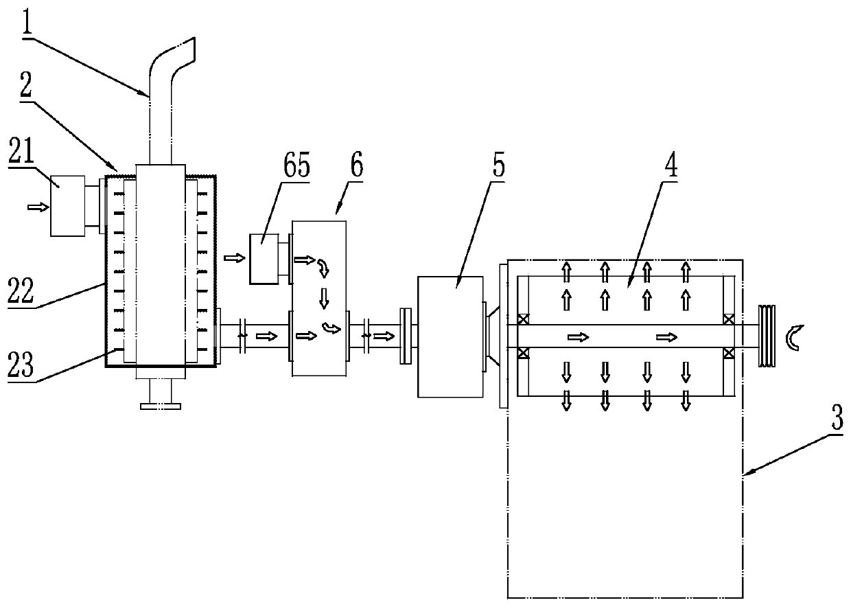
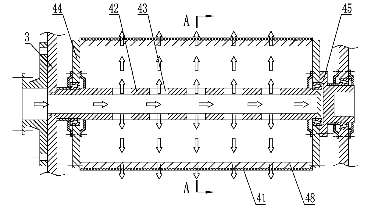
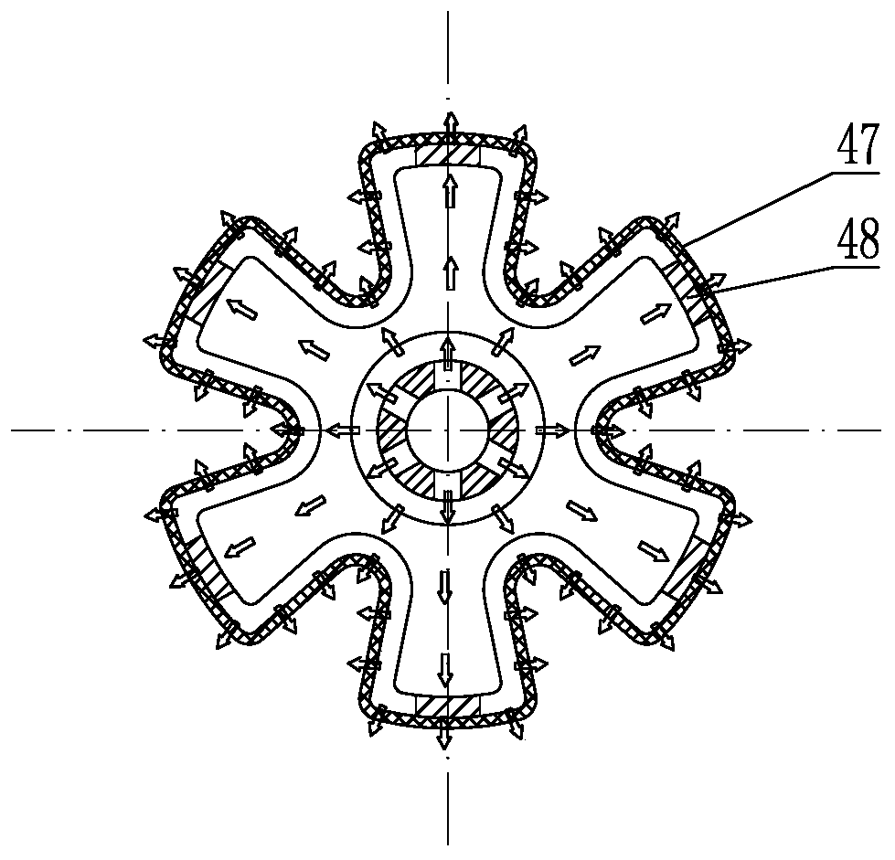
[0040] like Figure 1 to Figure 9 As shown, the waste heat drying system of the harvester includes a heat collecting device 2 correspondingly installed at the exhaust gas discharge device 1 and a drying device 4 installed on the top of the entrance of the granary 3, and the drying device 4 is arranged on the top of the entrance of the granary 3, It has a good drying effect witho...


PUM


Abstract

The invention discloses a harvester waste heat drying system.The harvester waste heat drying system comprises a heat collecting device and a drying device, wherein the heat collecting device is correspondingly arranged atthe position of an exhaust gas discharging device,and the drying device is arranged at the top of an granary inlet;a fan device is arranged on a granary,wherein the fan device used for communicating with the drying device and providing hot air,and an air distribution device is connected between the heat collecting device and the fan device; the air distribution device is usedfor ensuring the consistency of drying temperature and preventing an excessive drying effect caused by excessive drying temperature; the heat collecting device is used for collecting waste heat of theexhaust gas discharging device, and the fan device is used for transporting the waste heat collectedby the heat collecting device to the air distribution device and finally into the drying device todrygrains in the granary.The embodiment of the harvester waste heat drying systemis simple in structure, reasonable in design, the waste heat of the harvester can be recycled to dry the grains, the humidity of the grains is greatly reduced, the chance of mildew is further reduced, thus the storage time of the grains is prolonged, the cost of drying the grains at a later stage is lowered, and the energy utilization rate is improved.

Description

technical field [0001] The invention relates to the technical field of agricultural machinery, in particular to a drying system for a harvester. Background technique [0002] At present, the harvester has become a commonly used agricultural machinery when harvesting crops such as rice, wheat, corn, soybeans, etc., for harvesting, threshing, separating and cleaning, siloing and unloading the grain. However, after the traditional harvester is harvested and collected, because it does not have a drying device, the high value of free moisture and bound moisture carried by the grain itself is not evaporated. The time is short, so it is necessary to use special grain drying equipment to dry the grain or complete the grain drying to remove moisture by artificial exposure. Although the above methods can achieve the drying and drying of the grain, an additional grain dryer is used. The drying operation not only increases the energy consumption of the dryer, but also requires a lot of...

Claims


Application Information

Patent Timeline
Patent Type & Authority Applications(China)
IPC IPC(8): F26B9/06F26B21/00A01D45/02A01D45/04A01D45/00A23B9/08
CPCY02P60/85Y02P70/10Y02A40/90
Inventor 孙春静李衍国吴明清滕文建
Owner 青岛艾孚智能装备有限公司
Learn More