
Annular cylindrical breakwater externally connected with cylindrical grating and numerical calculation method of annular cylindrical breakwater

A calculation method and a cylindrical technology, applied in the direction of breakwaters, jetties, embankments, etc., can solve problems that have not yet been studied and applied by scholars at home and abroad, and achieve significant anti-wave effects, wide sources of materials, and easy construction.

Active Publication Date: 2019-06-21
DALIAN UNIV OF TECH
View PDF6 Cites 1 Cited by
  • Summary
  • Abstract
  • Description
  • Claims
  • Application Information

AI Technical Summary

Problems solved by technology

Among them, the open-cell structure has been gradually popularized and applied in port, coastal and offshore engineering due to its good characteristics of reducing wave reflection and wave force, and the open-cell structure with porous filling interlayer is a traditional open-cell structure. This kind of expansion has not been researched and applied by scholars at home and abroad.

Method used


Image

  • Annular cylindrical breakwater externally connected with cylindrical grating and numerical calculation method of annular cylindrical breakwater
  • Annular cylindrical breakwater externally connected with cylindrical grating and numerical calculation method of annular cylindrical breakwater
  • Annular cylindrical breakwater externally connected with cylindrical grating and numerical calculation method of annular cylindrical breakwater

Examples


Embodiment Construction

[0035] The application principle of the present invention will be further described below in conjunction with the drawings and simulation examples. It should be understood that the simulation examples described here are only used to explain the present invention, but not to limit the present invention.

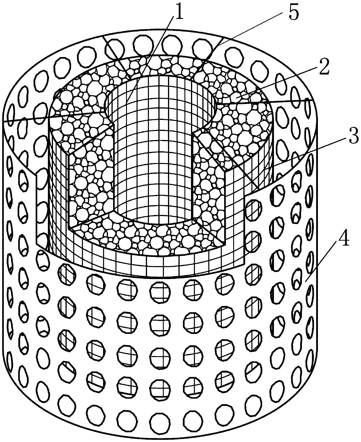
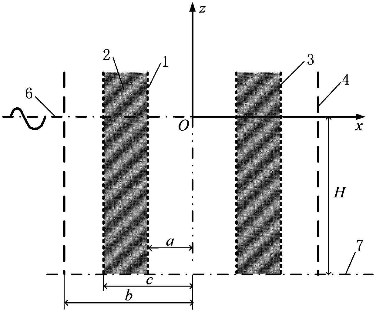
[0036] Reference attached Figure 1-12 The invention discloses a circular cylindrical wave-proof structure circumscribing a cylindrical grid. It includes the inner steel mesh 1, the porous stone filling layer 2, the outer steel mesh 3, the cylindrical grid 4, and the steel pipe beam 5. The porous stone filling layer 2 is located inside the cylindrical grid 4, clamped and fixed by the inner steel mesh 1, the outer steel mesh 3, the inner steel mesh 1, the outer steel mesh 3, and the cylindrical grid 4 are at any level The section is concentric rings. The porosity and linear resistance coefficient of the porous stone filling layer 2 are uniform, the opening coefficient of the cyl...


PUM


Abstract

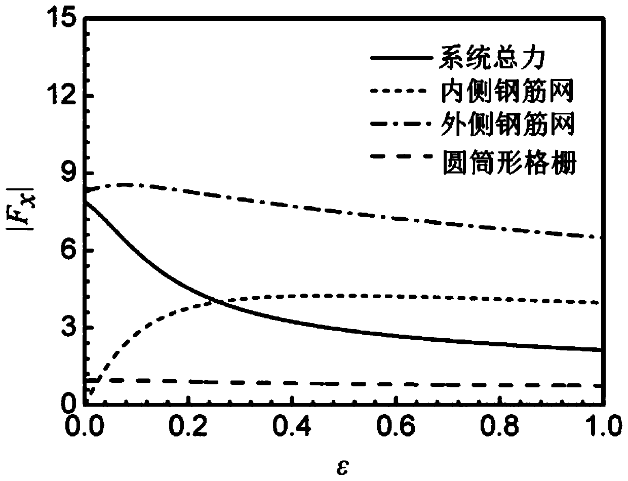
The invention discloses an annular cylindrical breakwater externally connected with a cylindrical grating and a numerical calculation method of the annular cylindrical breakwater, and belongs to the technical field of anti-wave structures. The annular cylindrical breakwater comprises inner and outer side reinforcing meshes, a porous stone filling layer, a cylindrical grating and steel pipe cross beams. The porous stone filling layer is located in the cylindrical grid and clamped and fixed by the inner and outer side reinforcing meshes, and the inner and outer side reinforcing meshes and the cylindrical grid are concentric rings on any horizontal section. The bottoms of the inner and outer side reinforcing meshes are fixedly connected with a seabed, and the externally-connected cylindricalgrid and the inner and outer side reinforcing meshes are fixedly connected through a plurality of the steel pipe cross beams. The stress of the annular cylindrical breakwater is calculated according to a proportional boundary finite element method, and the numerical value result shows that the annular cylindrical breakwater has good anti-wave performance. According to the breakwater, the perforated structure and the perforated structure with the porous filling interlayer are combined, the perforating coefficient and the filling coefficient are adjusted, the advantages of the perforated structure and the perforated structure with the porous filling interlayer are integrated, and the anti-wave effect is remarkable; and the perforated grid and the porous stone layer are mutually independent,so that the design is simple, and the construction is convenient.

Description

Technical field [0001] The invention belongs to the technical field of wave prevention structures, and relates to a circular cylindrical breakwater externally connected with a cylindrical grid. Specifically, it is capable of absorbing part of the wave force of seawater through a porous stone filling layer and a cylindrical grid, thereby A wave-proof structure that protects structures within the enclosed area from excessive wave forces. Background technique [0002] In recent years, with the development of industries such as marine oil and gas, marine transportation, marine fishery, coastal tourism, and marine new energy, more and more offshore structures have emerged, such as offshore drilling platforms, artificial islands, and large sea-crossing bridges. These marine structures play a pivotal role for economic development and social progress. However, due to the particularity of the environment, these structures are more susceptible to damage than land-based buildings. Various m...

Claims


Application Information

Patent Timeline
Patent Type & Authority Applications(China)
IPC IPC(8): E02B3/06E02B3/08
CPCY02A10/11
Inventor 刘俊臧全胜林皋叶文斌
Owner DALIAN UNIV OF TECH
Learn More