Cell separation system and method
A separation system and cell technology, applied in the field of cell separation, can solve the problems of high cost, affect the separation effect, and less harvest of stem cells, and achieve the effect of improving efficiency
- Summary
- Abstract
- Description
- Claims
- Application Information
AI Technical Summary
Problems solved by technology
Method used
Image


Examples
specific Embodiment approach 1
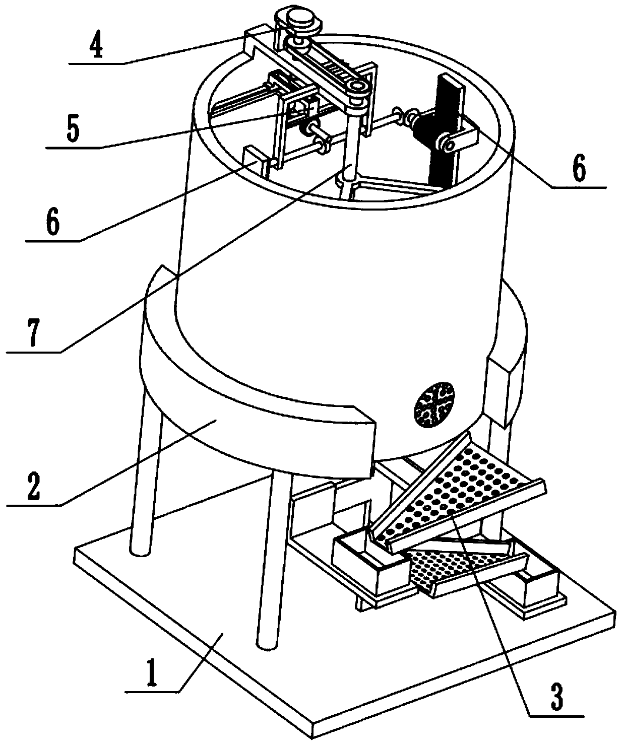
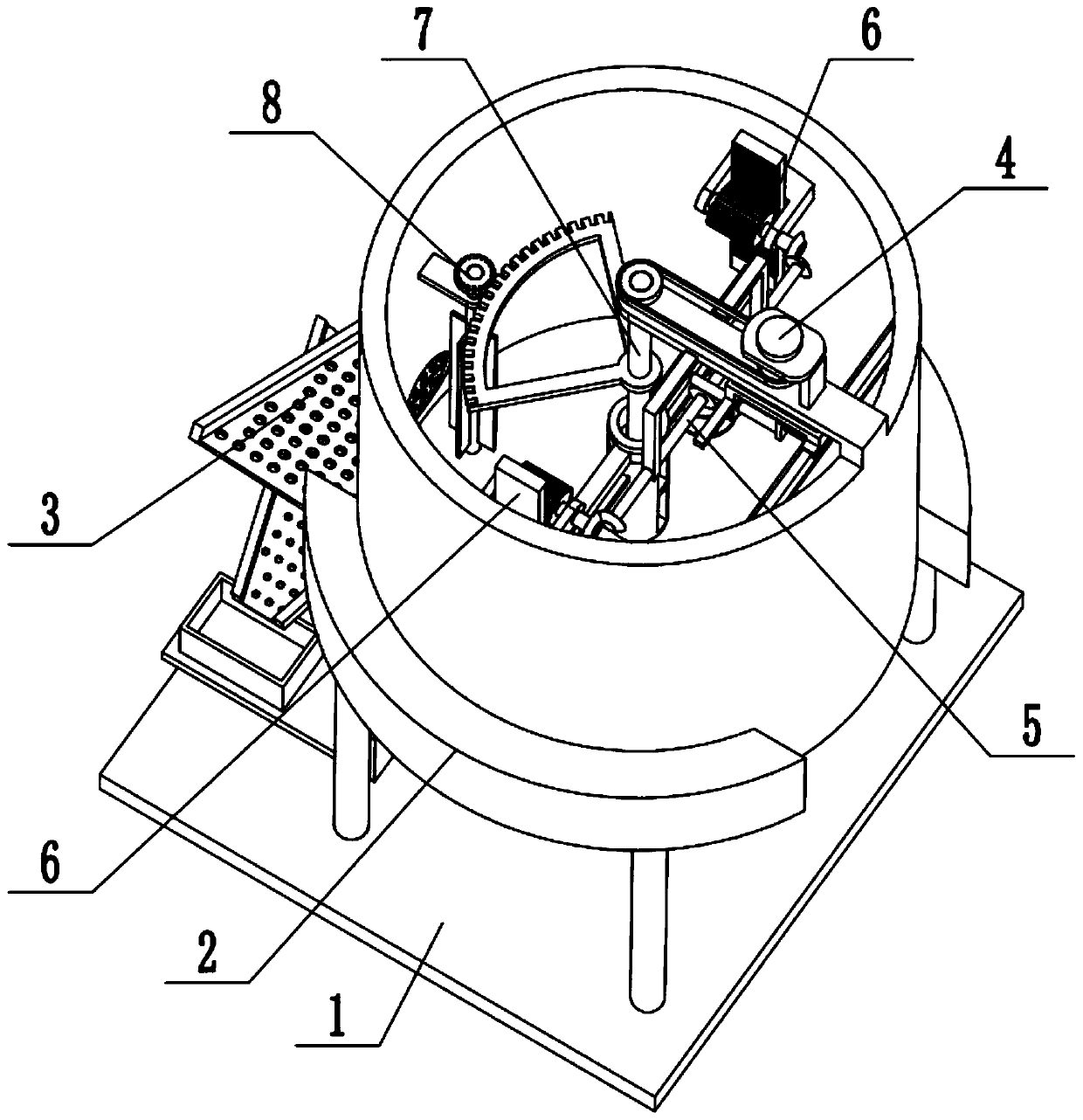
[0036] Combine below Figure 1-11 In this embodiment, a cell separation system includes a base 1, a separation cylinder assembly 2, a screening assembly 3, a power assembly 4, a reciprocating drive mechanism 5, a transmission wheel assembly 6, a stirring assembly 7 and an anti-clogging assembly 8. The separation cylinder assembly 2 is fixedly connected to the base 1, the screening assembly 3 is fixedly connected between the base 1 and the separation cylinder assembly 2, the power assembly 4 is fixedly connected to the upper end of the separation cylinder assembly 2, and the reciprocating drive mechanism 5 is fixedly connected to the separating The upper end of the cylinder assembly 2, the power assembly 4 is slidingly connected to the reciprocating drive mechanism 5, two transmission wheel assemblies 6 are provided, and the two transmission wheel assemblies 6 are symmetrically fixedly connected to the separation cylinder assembly 2, and the reciprocating drive mechanism 5 The ...
specific Embodiment approach 2
[0038] Combine below Figure 1-11 To illustrate this embodiment, the separation cylinder assembly 2 includes a separation cylinder body 2-1, a screen 2-2, an arc-shaped seat plate 2-3 and support legs 2-4; the front end of the separation cylinder body 2-1 is provided with The discharge through hole, the inner side of the discharge through hole is fixedly connected to the screen 2-2, the screen 2-2 is provided with a filter hole I, and the lower end of the separation cylinder body 2-1 is symmetrically fixedly connected to two arc-shaped seat plates 2- 3. The lower ends of the two arc-shaped seat plates 2-3 are respectively fixedly connected to the two support legs 2-4, and the four support legs 2-4 are all fixedly connected to the base 1. When the separation cylinder assembly 2 is in use, the mixed liquid is poured into the separation cylinder body 2-1, and the separated cells and waste liquid are discharged through the filter hole I on the screen 2-2.
specific Embodiment approach 3
[0040] Combine below Figure 1-11 To illustrate this embodiment, the screening assembly 3 includes a vertical plate 3-1, a horizontal plate 3-2, a first sieve plate 3-3, a second sieve plate 3-4, a side plate 3-5, and an L-shaped seat Plate 3-6, the first collection box 3-7 and the second collection box 3-8; the two ends of the vertical plate 3-1 are respectively fixedly connected to the separation cylinder body 2-1 and the base 1, and the front end of the vertical plate 3-1 Two horizontal plates 3-2 are fixedly connected, the first sieve plate 3-3 and the second sieve plate 3-4 are respectively fixedly connected to the two horizontal plates 3-2, and the second sieve plate 3-4 is located on the first sieve plate Below 3-3, the first sieve plate 3-3 is inclined to the lower left, the second sieve plate 3-4 is inclined to the lower right, and the left and right ends of the horizontal plate 3-2 are fixedly connected to a side plate 3-5 respectively. An L-shaped seat plate 3-6 is...
PUM
 Abstract
Description
Claims
Application Information
 - R&D
- Intellectual Property
- Life Sciences
- Materials
- Tech Scout
- Unparalleled Data Quality
- Higher Quality Content
- 60% Fewer Hallucinations
Browse by: Latest US Patents, China's latest patents, Technical Efficacy Thesaurus, Application Domain, Technology Topic, Popular Technical Reports.
© 2025 PatSnap. All rights reserved.Legal|Privacy policy|Modern Slavery Act Transparency Statement|Sitemap|About US| Contact US: help@patsnap.com