
A lower contact automatic current collector

A current collector and automatic technology, which is applied in the direction of current collectors, electric vehicles, power collectors, etc., can solve the problems of insufficient functions, poor stability, complex structure of the lower contact current collector, etc., to prevent damage to equipment and improve stability sexual effect

Active Publication Date: 2019-10-01
重庆中车四方所科技有限公司
View PDF1 Cites 0 Cited by
  • Summary
  • Abstract
  • Description
  • Claims
  • Application Information

AI Technical Summary

Problems solved by technology

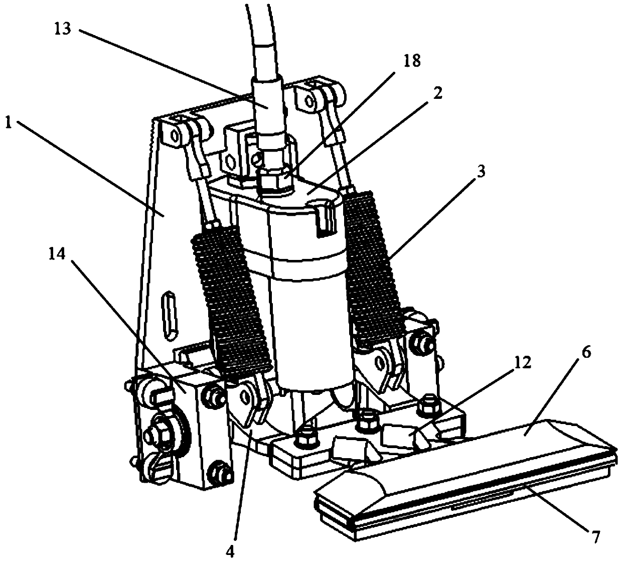
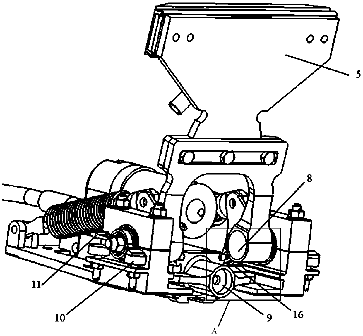
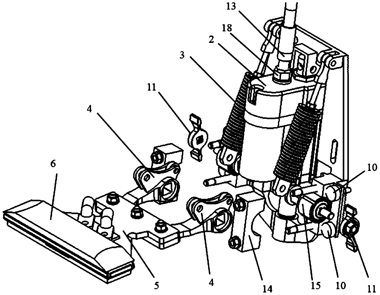
[0004] In view of the problems of complex structure, poor stability, high failure rate, large volume, insufficient functions and high maintenance cost of the lower contact current receiver in the prior art, the purpose of the present invention is to provide a simple structure, low failure rate, Small size, easy maintenance, and integrated functions such as automatic lifting bow, bow lowering lock, bow lowering position self-locking double protection, manual lifting bow, carbon skateboard contact force adjustable, carbon skateboard position height adjustable and other functions in one integrated lower contact automatic receiving streamer

Method used


Image

  • A lower contact automatic current collector
  • A lower contact automatic current collector
  • A lower contact automatic current collector

Examples


Embodiment Construction

[0046] All features disclosed in this specification, or steps in all methods or processes disclosed, may be combined in any manner, except for mutually exclusive features and / or steps.

[0047] Combine below Figure 1 to Figure 7 The present invention will be described in detail.

[0048]A lower contact automatic current receiver, including a frame 1, an electric push rod 2, a carbon slide 6 and a rotating arm 4, one end of the rotating arm 4 is hinged to the frame 1, and a tension spring 3 is connected to the rotating arm 4 , the other end of the extension spring 3 is connected to the frame 1, the electric push rod 2 is installed on the frame 1, and the electric push rod 2 is connected with a push block 9 for pushing the rotating arm 4 to rotate around the rotating shaft 8 , the carbon sliding plate 6 and the rotating arm 4 are fixedly connected through the insulating swing arm 5, and a copper bar 7 is arranged between the carbon sliding plate 6 and the insulating swing arm ...


PUM


Abstract

The invention belongs to the field of rail transit vehicle current collection devices and specifically relates to a lower contact automatic current collector. In order to solve problems of complicatedstructure, high fault rate, large size, incomplete functions, inconvenient maintenance and the like of the lower contact automatic current collector in the prior art, a technical scheme of the lowercontact automatic current collector is that the lower contact automatic current collector comprises a frame (1), an electric push rod (2), a carbon slide plate (6) and a rotating arm (4); one end of the rotating arm (4) is hinged to the frame (1); a tension spring (3) is also connected to the rotating arm (4); the other end of the tension spring (3) is connected with the frame (1); the electric push rod (2) is mounted on the frame (1); a push block (9) for pushing the rotating arm (4) to rotate around a rotating shaft (8) is connected to the electric push rod (2); and the carbon slide plate (6) is fixedly connected with the rotating arm (4) through an insulated swinging arm (5). The lower contact automatic current collector provided by the invention is suitable for the rail transit vehicleto dynamically collect current from a rigid power supply rail.

Description

technical field [0001] The invention belongs to the field of current collectors for rail transit vehicles, and in particular relates to a lower contact automatic current collector. Background technique [0002] The lower contact current collector is a kind of rigid power supply rail current collector. It is installed on the vehicle bogie to dynamically take current from the rigid power supply rail (third rail) for the train to meet the power demand of the train. equipment. At present, there are manual and automatic execution methods for the lower contact current collector, among which there are pneumatic and electric execution methods for automatic operation, and most of them are pneumatic execution methods. [0003] However, the structure of the lower contact current collector in the prior art is complex, there are many rotating mechanisms, and the force is unreasonable, resulting in a large device volume, high failure rate, and inconvenient repair and maintenance. For ex...

Claims


Application Information

Patent Timeline
Patent Type & Authority Patents(China)
IPC IPC(8): B60L5/39
Inventor 刘建谭宇文张大威蔡维谷翠军仇爽吴晓东马斌陈奎徐先伟张星张明广何贤吉
Owner 重庆中车四方所科技有限公司
Learn More