
Alloy smelting slag treatment equipment for overturning furnace

A technology for processing equipment and alloys, used in lighting and heating equipment, furnaces, crucible furnaces, etc., can solve the problems of difficult coordination, dangerous cleaning process, low efficiency, etc., to improve cleaning and storage efficiency, avoid high temperature damage, and facilitate recycling. The effect of using

Active Publication Date: 2019-06-18
宁夏宏丰特种合金有限公司
View PDF10 Cites 0 Cited by
  • Summary
  • Abstract
  • Description
  • Claims
  • Application Information

AI Technical Summary

Problems solved by technology

[0002] At present, during metal smelting, the turning furnace is the main equipment for a small amount of alloy smelting, usually around 1-1.5T. In the alloy smelting room, the impurities in the metal must be purified, usually adding detoxification to the molten metal. Slag agent, through stirring, the slag remover reacts with the molten metal, and the internal impurities are separated out and floated on the surface of the molten metal. Therefore, it is necessary to clean the scum. Usually, the scum is skimmed from the surface of the molten metal and placed In the slag collection box, usually when the scum is being skimmed, due to the high temperature, when the scum is skimmed and placed in the scum collection box, the scum box will be scoured severely, and the scum will not be cooled, making the scum collection The box is prone to thermal corrosion when it is heated. At the same time, when the dross is separated from the surface of the molten metal, it contains a residual part of the molten metal. In the slag collecting box, this part of the molten metal cannot be collected and reused, resulting in serious waste. When the smelting furnace is usually higher than the ground, the slag inclusion box needs to be lifted by a forklift when it is in use, and then the undertaking operation is carried out. During the process, the scum outside the skimming box was accidentally splashed. Due to the high temperature, it could not be cleaned immediately, and there was a difference in height, so it was difficult to clean it into the scum box. The cleaning process was dangerous.
[0003] Publication number CN105865211B discloses a smelting slag collection system, including a smelting slag collection device and a water slag pool. The semicircular pipe is supported by a bracket. The left part of the semicircular pipe has a slag outlet, and the left end of the semicircular pipe has a left baffle. There is a semi-circular groove on the left baffle, a right baffle at the right end of the semi-circular tube, and a round hole in the middle of the right baffle. Two side plates are respectively welded on the right end of the semi-circular tube. The upper part of the plate is welded; the lower part of the right baffle and the left baffle are respectively welded with a bearing frame, and the two bearing seats are installed on the two bearing frames respectively. There are sealing rings and bearings in the two bearing seats, and the shaft consists of two Supported by bearings in a bearing seat; there is a slag pushing thread on the shaft located in the semicircular pipe, and the pulley is installed on the left end of the shaft; the bottom plate of the slag pool forms a certain angle with the horizontal line, and there is an overflow pipe on one side wall of the slag pool. , the slag material tank is installed on the right wall of the slag material tank, and there is a water outlet pipe at the right end of the slag material tank. Cooperate, can not carry out the recovery of molten metal

Method used


Image

  • Alloy smelting slag treatment equipment for overturning furnace
  • Alloy smelting slag treatment equipment for overturning furnace
  • Alloy smelting slag treatment equipment for overturning furnace

Examples


Embodiment Construction

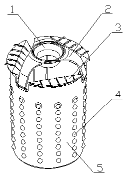
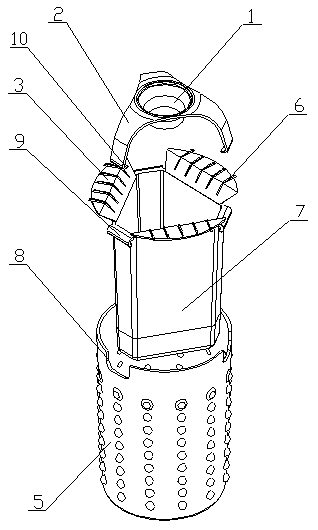
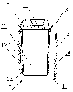
[0016] The slag treatment equipment for the alloy smelting of the overturning furnace of the present invention is realized in the following way: the slag treatment equipment for the alloy smelting of the overturning furnace of the present invention consists of a material guide ring (1), a box cover (2), a side material guide plate (3), and a spherical convex (4) , water bath box (5), guide bar (6), inner storage box (7), installation hanging groove (8), hanging buckle (9), connecting arm (10), accommodation cavity (11), filter plate ( 12), the bottom liquid collection tray (13) and the connecting buckle (14), the mouth of the water bath box (5) has three installation hanging slots (8) at equal angles, and the width of the installation hanging slots (8) It gradually decreases from the outside to the inside. The installation hanging groove (8) is provided with a non-slip pad on the groove wall, and the box cover (2) is placed above the mouth of the water bath box (5). The outer s...


PUM


Abstract

The invention relates to alloy smelting slag treatment equipment for an overturning furnace and discloses metal dross treatment box equipment for draining, collecting and reclaiming molten metal through a multi-layered box body structure by filling the middle with cooling water for water bath cooling and matching a filter plate. The equipment is characterized in that three mounting hanging slots are formed in the mouth of a water bath box at equal angles; the mounting hanging slots are gradually reduced from outside to inside in width; anti-skid pads are arranged on the walls of the mounting hanging slots; a box cover is placed above the mouth of the water bath box; three supporting arms extend downward in arc shapes on the outer side of the box cover, separately, and one ends of the supporting arms extend o the three mounting hanging slots, separately, connecting clamping arms are arranged at one ends of the supporting arms, included angles are formed between the connecting clamping arms and the supporting arms and are acute angles; a plurality of thorns are arranged on the connecting clamping arms; the thorns are of triangular pyramid structures; an inner accommodating box is placed in the water bath box; and three buckles are separately put at the mouth of the inner accommodating box and are separately hung on the connecting clamping arms of the three supporting arms.

Description

technical field [0001] The invention discloses an alloy smelting slag processing equipment for an inversion furnace, which relates to a treatment box device for collecting scum after slag cleaning in an inversion furnace during the metal smelting process, and belongs to the field of metal processing. In particular, it relates to a metal scum processing box equipment with a multi-layer box structure, filled with cooling water in the middle to cool down in a water bath, and cooperating with a filter plate to drain and collect molten metal for recycling. Background technique [0002] At present, during metal smelting, the turning furnace is the main equipment for a small amount of alloy smelting, usually around 1-1.5T. In the alloy smelting room, the impurities in the metal must be purified, usually adding detoxification to the molten metal. Slag agent, through stirring, the slag remover reacts with the molten metal, and the internal impurities are separated out and floated on ...

Claims


Application Information

Patent Timeline
Patent Type & Authority Applications(China)
IPC IPC(8): F27B14/08F27D3/15
Inventor 不公告发明人
Owner 宁夏宏丰特种合金有限公司
Learn More