
Goaf grouting method based on pinnate horizontal branch directional drilling technology

A technology of horizontal branching and goaf, which is applied in the direction of earthwork drilling, mining equipment, shaft lining, etc., and can solve the problems of solid pipe work and large material consumption, difficulty in moving vertical drilling, and large material consumption, etc. Achieve the effects of avoiding areas that are difficult to drill, reducing the amount of drilling work and improving engineering efficiency

Inactive Publication Date: 2019-06-18
XIAN RES INST OF CHINA COAL TECH& ENG GROUP CORP
View PDF7 Cites 14 Cited by
  • Summary
  • Abstract
  • Description
  • Claims
  • Application Information

AI Technical Summary

Problems solved by technology

[0004] ①Large project volume and high project cost
[0006] ③High pipe fixing work and material consumption
Due to the large number of drilling holes, pipe fixing work is required for each drilling hole, resulting in huge material consumption and greatly increasing the project cost
[0007] ④In some areas with complex surface conditions, such as existing buildings (structures), water bodies, large terrain fluctuations, woodland and other surface obstacle areas, vertical drilling construction has problems such as difficulty in moving and delaying the construction period
At the same time, considering the influence range of the overburden rock movement angle and the width of the safety protection belt, the area of ​​goaf treatment is often far beyond the land acquisition scope of the proposed (structure) buildings, resulting in temporary land acquisition problems

Method used


Image

  • Goaf grouting method based on pinnate horizontal branch directional drilling technology
  • Goaf grouting method based on pinnate horizontal branch directional drilling technology
  • Goaf grouting method based on pinnate horizontal branch directional drilling technology

Examples


Embodiment Construction

[0034] The present invention will be described in detail below in conjunction with the accompanying drawings and specific embodiments.

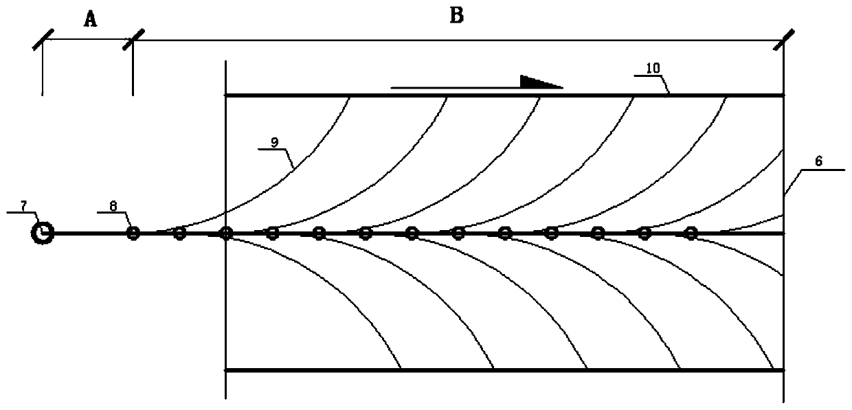
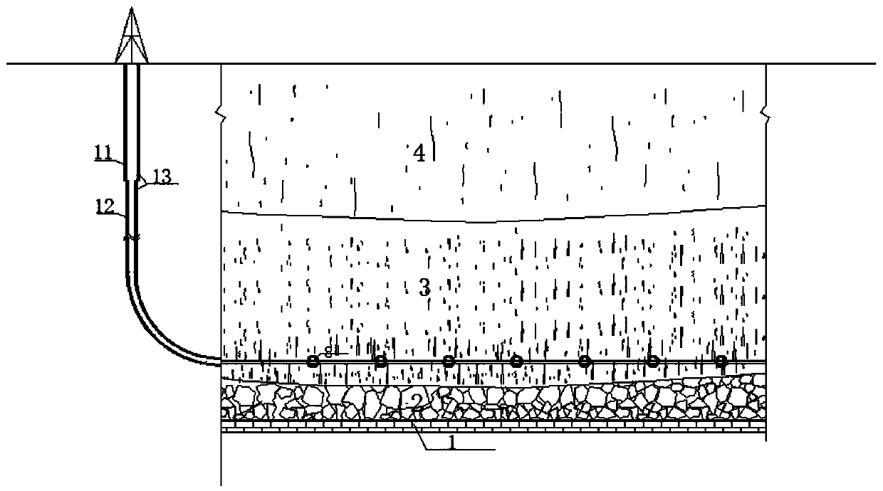
[0035] see figure 2 and image 3 , shows the goaf grouting method based on the plume horizontal branch directional drilling process of the present invention.

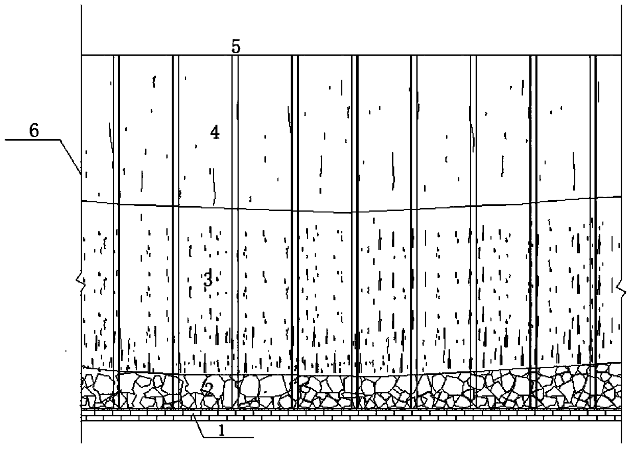
[0036] The gob grouting method based on the pinnate horizontal branch directional drilling process targets the fully mechanized gob as well. figure 1 As shown, the fully-mechanized gob has a caving zone 2, a fissure zone 3, and a curved subsidence zone 4 on the coal seam floor 1 within the control area boundary 6, and the caving zone 2 has a large number of different sizes. Rockfall, the caving zone bears the fissure zone 3 and the curved subsidence zone 4. In order to realize the smooth grouting in the fully mechanized goaf, the construction of pinnate horizontal branch directional drilling was pioneered. Specifically, In other words, the goaf grouting method includes the followin...


PUM


Abstract

The invention discloses agoaf grouting method based on pinnate horizontal branch directional drilling technology. The goaf grouting method based on pinnate horizontal branch directional drilling technology comprises the following steps thatstep 1, drilling is arranged, specifically,pinnate horizontal branch directional drilling is designed in a treatment area of a fully mechanized goaf, a verticalsection, a deflecting section, and afissure zone horizontal extension section; step 2, a grouting material is determined, and the grouting material consists of cement, flyash or clay, and an accelerator; step 3, drilling and grouting operations of each directional drilling are conducted, a drill tool is first lowered and drills into the vertical section and the deflecting section, and a forward drilling grouting ishorizontally conducted.Thus, according to the goaf grouting method based on pinnate horizontal branch directional drilling technology,disadvantages of vertical drilling technology in fully mechanized working face goaf grouting technology are overcome, the pinnate horizontal branch directional drilling is constructed from the earth surface to the lower middle layer of the fissurezone, grout is filled and strengthening is conducted on goaf caving zone rock mass, underground residual cavities, and fissures, activation space of an old goafis thoroughly eliminated, and thegoaf treatment is more effective.

Description

technical field [0001] The invention relates to the technical field of geological disaster prevention and control in goafs, in particular to a goaf grouting method based on a pinnate horizontal branch directional drilling process. Background technique [0002] After 2010, the proportion of comprehensive mechanized coal mining (referred to as "mechanized mining") in my country's coal mines has increased significantly. The fully mechanized goaf has a large area, the roof has fully collapsed, and the development of the "three zones" is relatively regular. After a long period of natural compaction, the underground space after mining has gradually reached a state of "stress balance". When the construction of buildings (structures), seismic activity, and strong drainage of groundwater occur above the area, the equilibrium state is broken, the old goaf is "activated", the rock mass in the caving zone and fracture zone is re-compacted, and the remaining underground cavities are re-...

Claims


Application Information

Patent Timeline
IPC IPC(8): E21D11/10C04B28/00
Inventor 刘天林刘小平王玉涛白仲荣张宝元曹晓毅赵文豪刘浩琦刘新星田延哲陈超张鑫李珊
Owner XIAN RES INST OF CHINA COAL TECH& ENG GROUP CORP
Learn More