An electromagnetic type ultra-thin-wall pipe multi-diameter segmental bending forming device

A bending forming and ultra-thin-walled technology, which is applied in the cold processing of metal materials and engineering materials processing and forming, can solve the problems of the applicability of heavy bending pipe forming mechanisms, the inability to change the bending angle, and poor processing quality of thin-walled pipes, so as to avoid Cracks on the outside and excessive accumulation or wrinkling on the inside, the effect of improving processing, and the effect of avoiding processing defects

Active Publication Date: 2020-07-28
ZHEJIANG UNIV
View PDF5 Cites 0 Cited by
  • Summary
  • Abstract
  • Description
  • Claims
  • Application Information

AI Technical Summary

Problems solved by technology

In this process, not only the equipment is cumbersome, but also the bending angle cannot be changed due to the single mold
Especially in some special occasions, the equipment is limited, and the cumbersome pipe bending mechanism shows insufficient applicability
At the same time, the processing quality of thin-walled pipes is poor, and processing defects are prone to occur
In addition, during the process of concentrated deformation force, the pipe may appear unstable and wrinkled due to excessive accumulation of material

Method used


Image

  • An electromagnetic type ultra-thin-wall pipe multi-diameter segmental bending forming device
  • An electromagnetic type ultra-thin-wall pipe multi-diameter segmental bending forming device
  • An electromagnetic type ultra-thin-wall pipe multi-diameter segmental bending forming device

Examples


Embodiment Construction

[0024] The present invention will be further described below with reference to the drawings and embodiments.

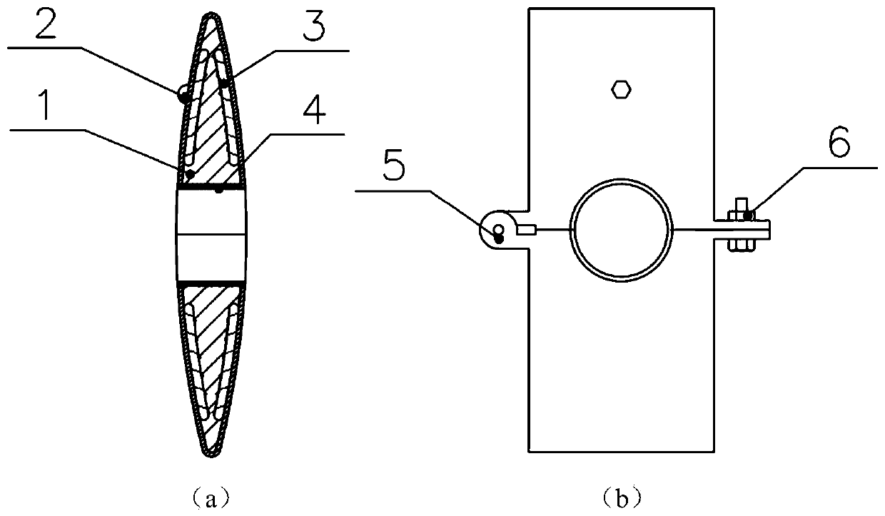
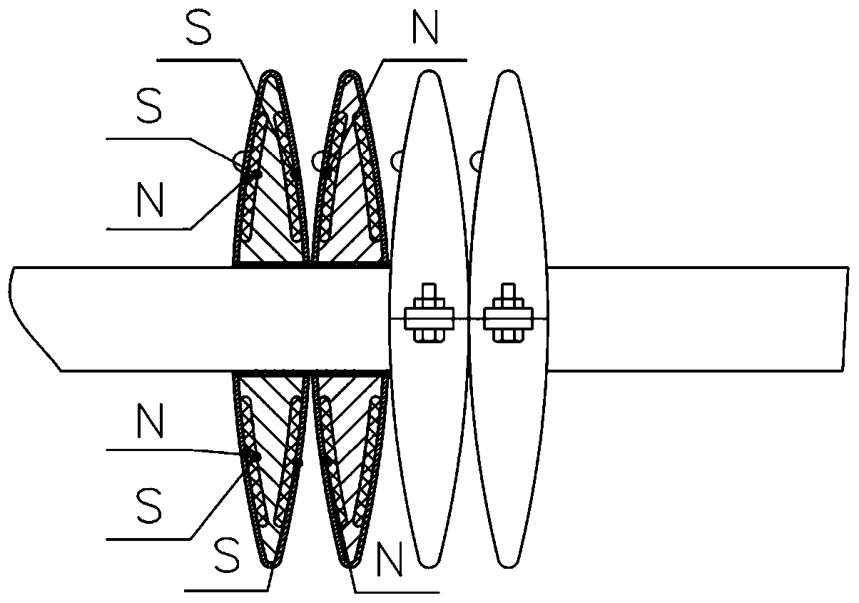
[0025] Such as figure 1 As shown in (a), the specific implementation of the present invention includes a plurality of basic unit bodies with the same structure set on a pipe. Each basic unit body is mainly composed of a base 1, a limiting protrusion 2 and an electromagnet 3. The base 1 is divided into The two sub-bases of the two parts are in a spindle shape after being butted, so that the two sub-bases face arc surfaces on both sides of the pipe axis. Each sub-base is in the shape of a half spindle. Outside the pipe, the base 1 viewed along the axial direction of the pipe has a square shape, and the base 1 viewed along the radial side of the pipe has a spindle shape, and its shape is derived from a round bisected spindle. The base body 1 has an arc-shaped outer surface, which is obtained by making a spindle-shaped circular bisector.

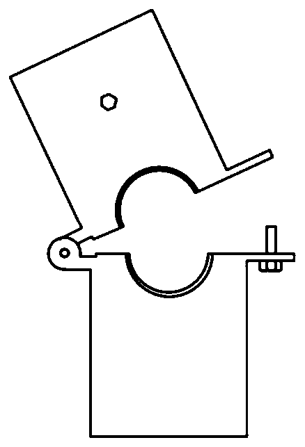
[0026] Such as figure 1 (b) and fig...


PUM


Abstract

The invention discloses an electromagnetic ultra-thin-wall pipe multi-bending-diameter sectional bending forming device. The device comprises a plurality of basic unit bodies which are arranged on a pipe in a sleeving mode and are the same in structure, each basic unit body is mainly composed of a base body, limiting protrusions and electromagnets, the base body is divided into two sub base bodieshalf-and-half, semicircular holes are formed in the middles of the contact end surfaces of the two sub base bodies correspondingly, the semicircular holes are in butt joint to form a through hole forallowing the pipe to penetrate therethrough to be installed, the electromagnets are arranged in the two sides of each of the two sub base bodies, the magnetic pole polarity directions of the electromagnets are in the axial direction of the pipe, and the limiting protrusions are arranged on the surfaces of the two sides of each of the two sub base bodies. According to the device, the acting forcedistribution is more uniform compared with that of a traditional pipe bending mechanism, the bending processing quality of the pipe is improved, the device is suitable for processing of the ultra-thin-wall pipes and pipe bending operation at the assembling field, the processing plane can be changed, all the unit bodies can be located at different planes according to requirements, and the spatial arbitrary curve bending processing of the pipes can be realized at the assembling field.

Description

Technical field [0001] The invention belongs to the technical field of engineering material processing and molding, and specifically belongs to the technical field of cold processing of metal materials. It can realize multi-bending plane curve segmental bending of ultra-thin-walled pipes, or real-time bending processing of space curves on site. Background technique [0002] With the needs of engineering, in more and more applications, metal pipes need to be bent as needed during processing. This process belongs to the technical field of cold working of metal materials, and cold working refers to a processing technique that plastically deforms metals below the recrystallization temperature. By applying a deforming force to the pipe, the shape of the pipe can be changed within the range allowed by the material to obtain the desired shape. [0003] At present, common pipe bending devices mostly use hydraulic driving methods, and the equipment is relatively heavy and requires high pi...

Claims


Application Information

Patent Timeline
Patent Type & Authority Patents(China)
IPC IPC(8): B21D26/14B21D7/16
Inventor 伊国栋晋哲楠张绍举
Owner ZHEJIANG UNIV
Why Eureka
Try Eureka