Installation device for outdoor shooting camera and application method thereof
A technology for installing devices and cameras, which is applied in the direction of supporting machines, mechanical equipment, machine tables/brackets, etc., which can solve problems such as inability to install quickly, human and physical losses, and large environmental restrictions, and achieve high practicability, durability, and anti-theft Good effect and strong corrosion resistance
- Summary
- Abstract
- Description
- Claims
- Application Information
AI Technical Summary
Problems solved by technology
Method used
Image
Examples
Embodiment 1
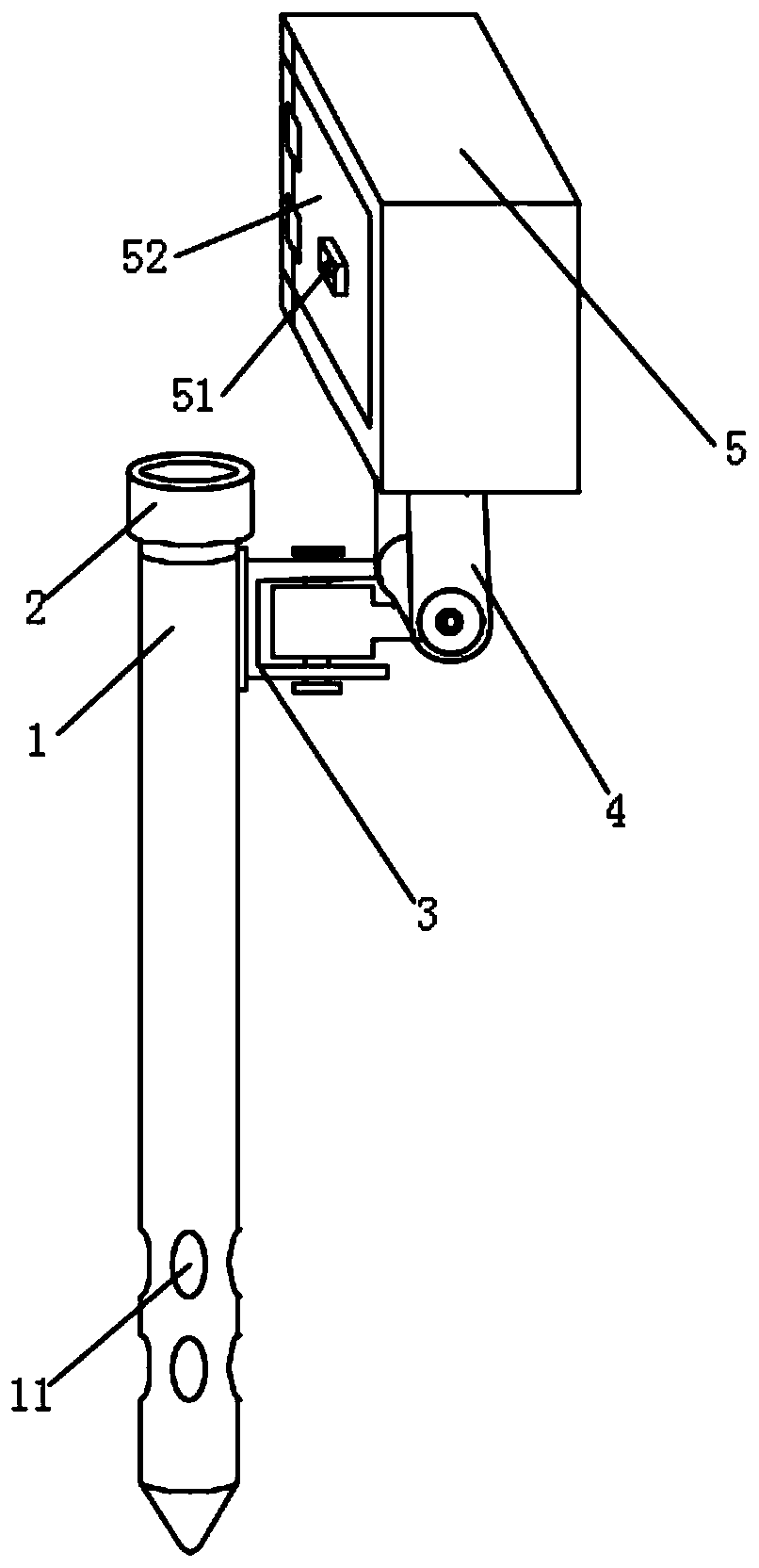
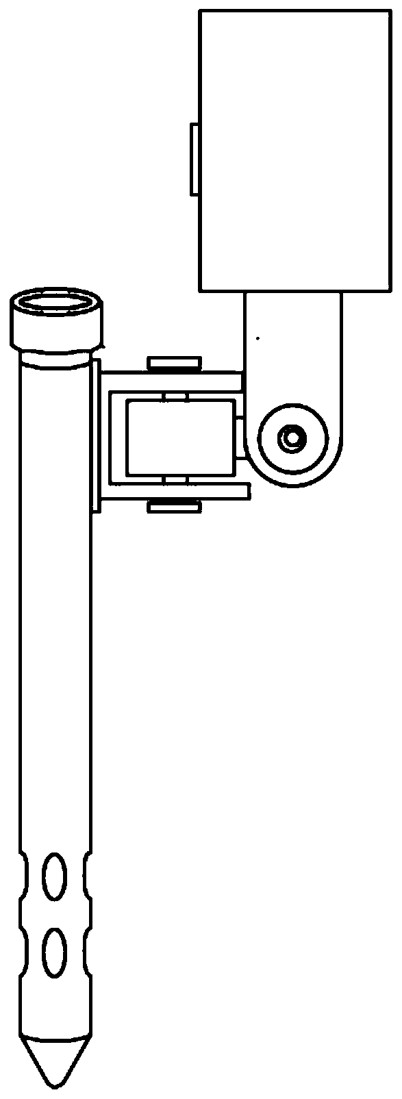
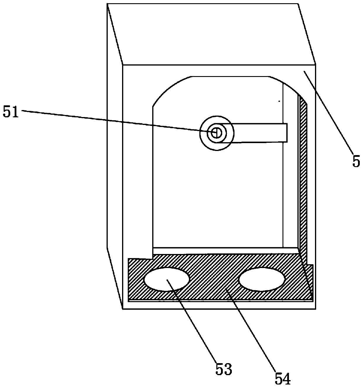
[0033] Such as figure 1 , figure 2 As shown, a mounting device for shooting a camera in the field includes a post 1, the upper end of the post 1 is threadedly connected with a sealing cap 2, and the outer surface of the post 1 is welded with a connecting turntable 3 at a position close to the sealing cap 2. The other end of the turntable 3 is fixedly installed with a connecting column 4, which rotates through the connecting turntable 3. The function of the connecting column 4 is to connect the anti-theft box 5 and the connecting turntable 3. The connecting turntable 3 is composed of upper, middle and lower plates. The body is a fixed structure, and the middle disk body is connected with the other two disk bodies by the center of the rotating shaft, so that the middle disk body can rotate freely. The connecting column 4 is a cylinder in the embodiment. The structure of the anti-theft box 5, the outer surface of the upper end of the connecting column 4 is welded with an anti-t...
Embodiment 2
[0036] On the basis of above-mentioned embodiment 1, as image 3 Figure 4 and Figure 5 As shown, the post 1 is divided into an outer shell 12 and an inner tube 14. The inner tube 14 is fixedly connected to the outer shell 12 through the lower end. There is a gap between the inner walls of the outer casing 12, and an impact tube 13 is placed between the gaps. The upper end of the impact tube 13 can be connected with the inner thread of the sealing cap 2. The thickness of the impact tube 13 needs to ensure that it can move freely up and down in the gap, and the impact The lower end of the pipe 13 is a sharp end. In this embodiment, the filling of cement is inserted from the upper port of the inner pipe 14, and the outlet hole 11 runs through the outer casing 12 and the inner pipe 14 to ensure that the cement can flow out of it. When removing the post 1, the sealing cap 2 can be opened, the impact tube 13 can be taken out, and the impact tube 13 can be connected with a mechan...
Embodiment 3
[0038] On the basis of the above-mentioned embodiment 2, two improvements are made. One, the connecting seal 15 is pasted in the gap between the inner tube 14 and the outer shell 12. The seal 15 can be made of a material that is easy to be cut such as rubber, The seal 15 can prevent the cement from overflowing into the gap when it passes through the outlet hole 11. Second, it can help the impact tube 13 to be placed on the surface of the seal 15. By using the screw connection method between the seal cap 2 and the impact tube 13 in Embodiment 2, there may be Certainly complicated, setting the sealing member 15 can make the impact tube 13 placed, easy to use, and the rubber material can make the impact tube 13 easy to break.
PUM
 Abstract
Description
Claims
Application Information
 - Generate Ideas
- Intellectual Property
- Life Sciences
- Materials
- Tech Scout
- Unparalleled Data Quality
- Higher Quality Content
- 60% Fewer Hallucinations
Browse by: Latest US Patents, China's latest patents, Technical Efficacy Thesaurus, Application Domain, Technology Topic, Popular Technical Reports.
© 2025 PatSnap. All rights reserved.Legal|Privacy policy|Modern Slavery Act Transparency Statement|Sitemap|About US| Contact US: help@patsnap.com


