Automatic heat preservation building block production line

A self-insulating block and production line technology, which is applied in ceramic molding workshops, unloading devices, ceramic molding machines, etc., can solve the problem of difficult positioning of the mold lifting device, inaccurate positioning of the pressure head and the mold, and the occupation of the block curing room Large area and other problems, to achieve the effect of high equipment reliability, stable and reliable equipment operation, and stable lifting

Pending Publication Date: 2019-06-11
山东祀方机械有限公司
View PDF2 Cites 0 Cited by
  • Summary
  • Abstract
  • Description
  • Claims
  • Application Information

AI Technical Summary

Problems solved by technology

Because the weight of the mold is very large, the independent action of the four mold lifting devices can easily lead to asynchronous lifting actions, resulting in radial force on the oil cylinder, easy deviation of the oil cylinder, and easy damage to the oil cylinder. It is difficult for the device to be positioned accurately with the mold, resulting in inaccurate positioning of the indenter and the mold, which affects demoulding
[0006] The second secondary technical problem to be solved by the present invention is: the existing block curing room adopts the design of a plurality of curing bins arranged side by side indoors. Due to the large production volume of blocks, the block curing room is located in the entire production line. The floor area is very large; and the existing block curing room is inconvenient to move the mold when the block mold is discharged into the curing chamber
The distributors in the prior art cannot meet the production requirements and cannot achieve uniform distribution

Method used


Image

  • Automatic heat preservation building block production line
  • Automatic heat preservation building block production line
  • Automatic heat preservation building block production line

Examples


Embodiment Construction

[0058] The present invention will be further described below in conjunction with accompanying drawing by non-limiting embodiment:

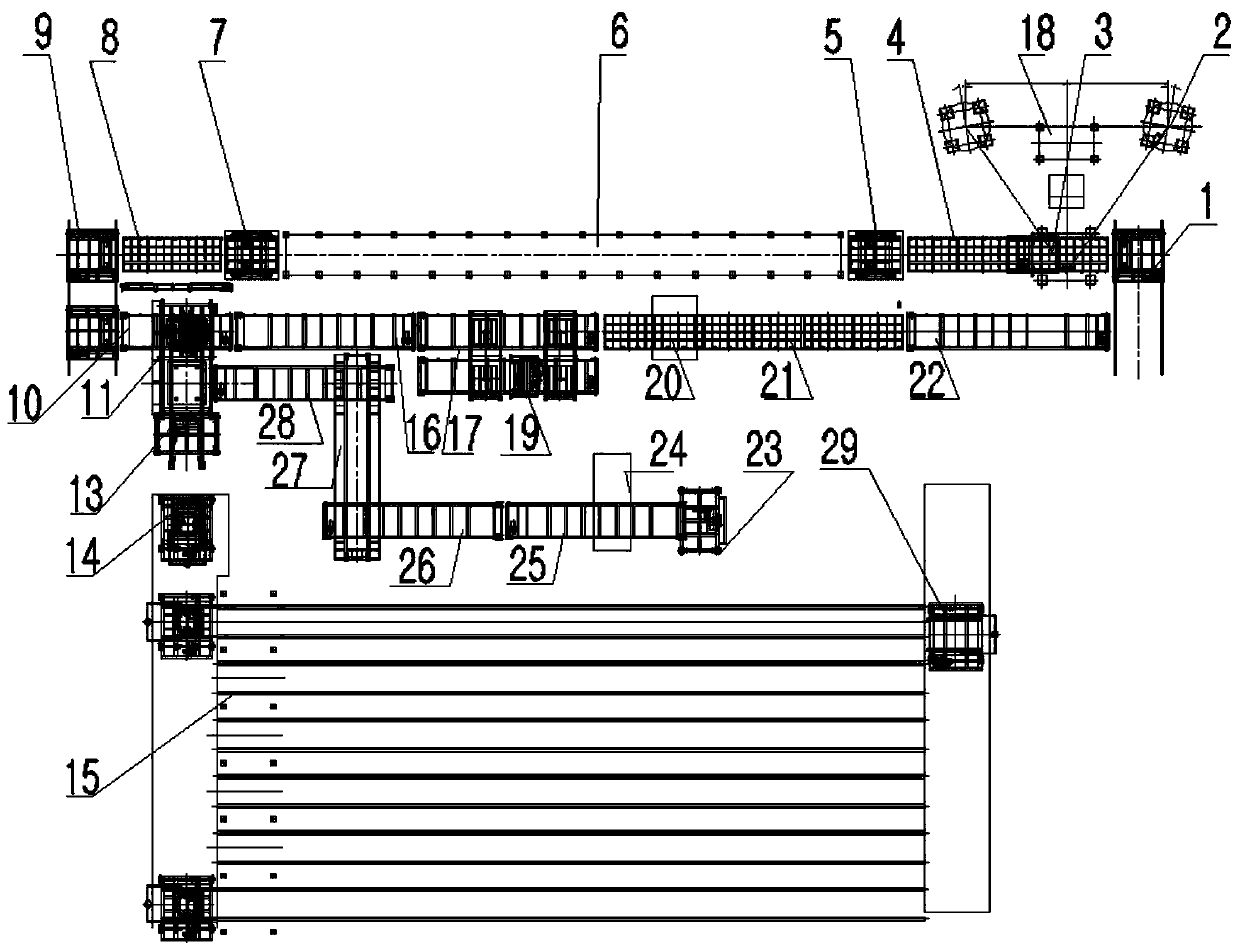
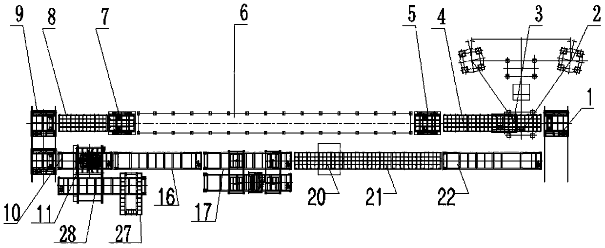
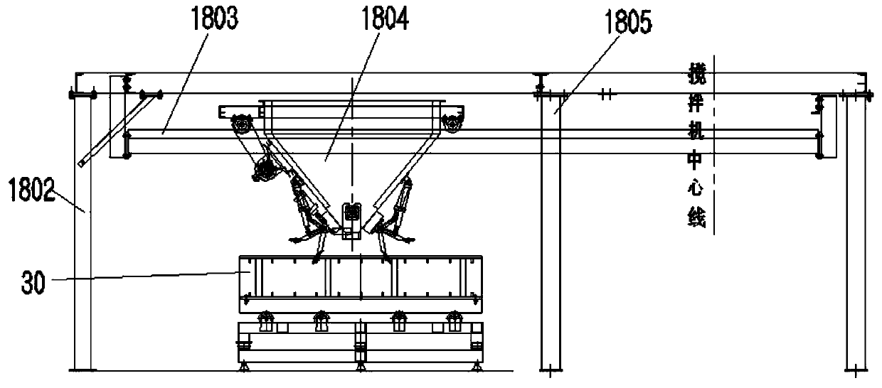
[0059] as attached figure 1 As shown, it is a fully automatic self-insulating block production line, which includes a mixer 2 for mixing materials, a distributor device 18 arranged below the mixer 2, and a 1# power transmission device is arranged below the distributor device 18 4. A vibrating device 3 is installed at the lower part of the 1# power conveying device 4, and a 1# hoist 5, a block curing room 6, and a 2# hoist 7 are sequentially arranged on the rear side of the 1# power conveying device 4 along the mold travel direction , 2# power conveying device 8, demoulding device 11, 1# roller chain conveyor 10 is arranged at the bottom of demoulding device 11, between the tail end of 2# power conveying device 8 and the head end of 1# roller chain conveyor 10 There is a 2# ferry car 9 between them, and a return track for returning to the 1# power...


PUM


Abstract

The invention discloses an automatic heat preservation building block production line. The automatic heat preservation building block production line comprises a stirrer and a distributor device. A 1#power conveying device is arranged below the distributor device, and a vibration device is arranged on the lower portion of the 1# power conveying device. A 1# elevator, a building block curing room,a 2# elevator, a 2# power conveying device and a demoulding device are sequentially arranged on the rear side of the 1# power conveying device. A return rail for returning the 1# power conveying device is arranged on the rear side of the demoulding device, and a cleaning device and a spraying device are sequentially arranged on the return rail. A 1# roll chain conveyor is arranged on the lower portion of the demoulding device, and the tail end of the 1# roll chain conveyor is in butt joint with the return rail. A 2# shuttle bus is arranged between the tail end of the 2# power conveying deviceand the head end of the 1# roll chain conveyor, and a 1# shuttle bus is arranged between the tail end of the return rail and the head end of the 1# power conveying device. A 8# roll chain conveyor parallel to the 1# roll chain conveyor is arranged on the side of the demoulding device, and a heat preservation building block cork base carrying device is arranged above the 8# roll chain conveyor.

Description

technical field [0001] The invention relates to a self-insulating block production line, which is mainly used for the production of self-insulating blocks and belongs to the technical field of heat-insulating block production equipment. Background technique [0002] With the development of the economy and the progress of the society, energy conservation has become a consensus, and building energy conservation is an important field of energy conservation work. With the continuous improvement of building energy-saving standards, thermal insulation blocks are used more and more widely as building energy-saving materials. [0003] With the continuous increase in the demand for thermal insulation blocks, in order to improve production efficiency, the use of automatic block production lines to produce thermal insulation blocks has become the first choice for many manufacturers. [0004] The publication number is CN104325553 A, and the name is a Chinese patent application for an a...

Claims


Application Information

Patent Timeline
Patent Type & Authority Applications(China)
IPC IPC(8): B28B15/00B28B11/24B28B13/06
Inventor 夏锋马俊霞尹承保
Owner 山东祀方机械有限公司
Why Eureka
Try Eureka