
Vortex separation device and control method thereof

A separation device and control method technology, applied in separation methods, filtration separation, chemical instruments and methods, etc., can solve the problems of high labor intensity, large cutting fluid reserves, large consumption and waste, etc., to achieve good cooling effect, avoid Reserve and take up space, improve the effect of recycling efficiency

Inactive Publication Date: 2019-06-11
浙江吉宝智能装备股份有限公司
View PDF4 Cites 0 Cited by
  • Summary
  • Abstract
  • Description
  • Claims
  • Application Information

AI Technical Summary

Problems solved by technology

[0004] The invention mainly solves the problems of high manual work intensity, frequent maintenance, large cutting fluid reserve, large consumption and waste and short service life in the prior art, and provides a vortex separation device and its control method. The vortex separation device It has the advantages of compact structure, complete functions, good cooling effect of coolant, simple and labor-saving operation, energy saving and environmental protection, convenient use and maintenance and long service life

Method used


Image

  • Vortex separation device and control method thereof
  • Vortex separation device and control method thereof
  • Vortex separation device and control method thereof

Examples


Embodiment Construction

[0027] The technical solution of the invention will be further specifically described below through the embodiments and in conjunction with the accompanying drawings.

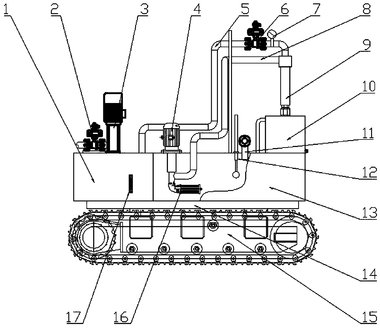
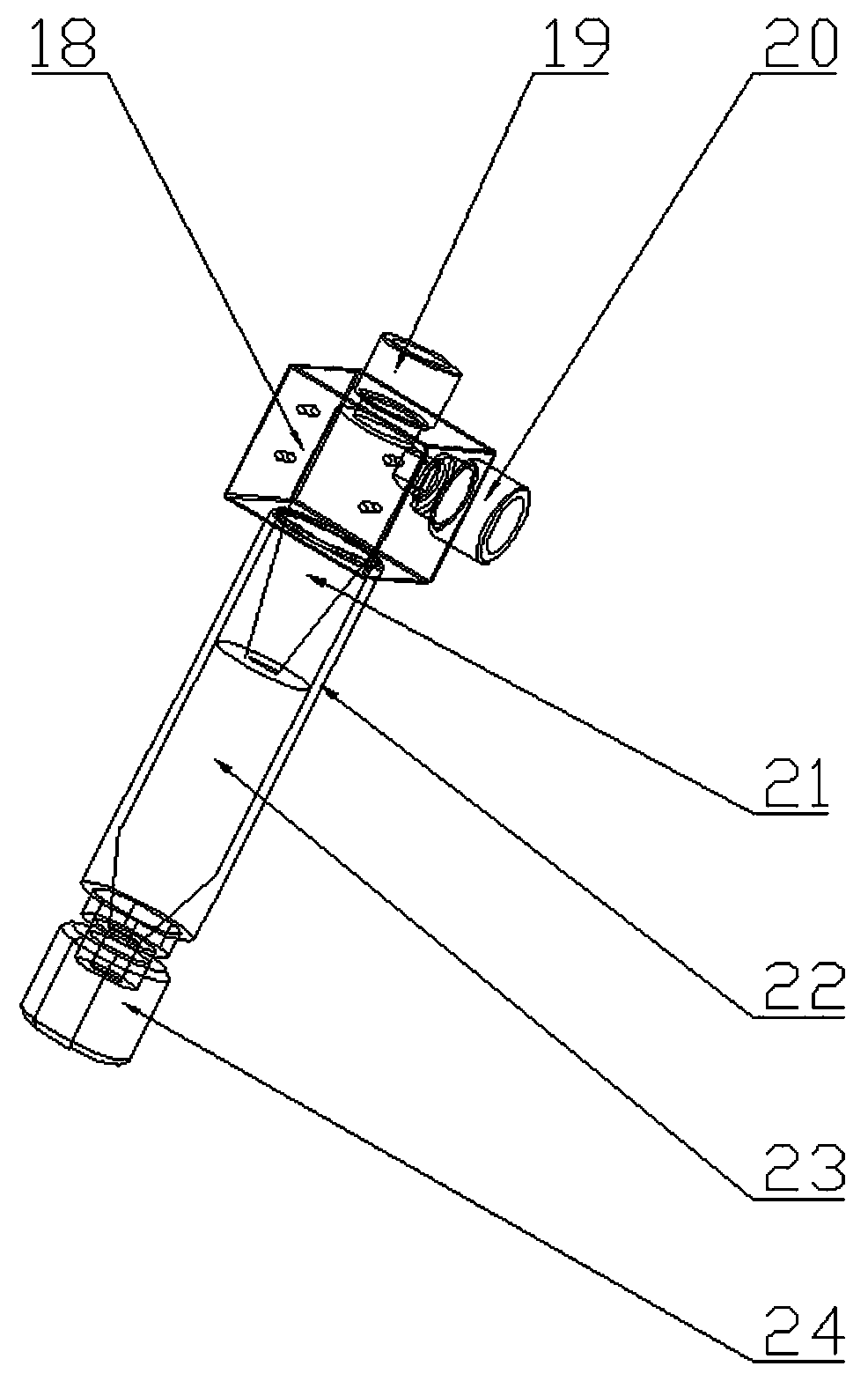
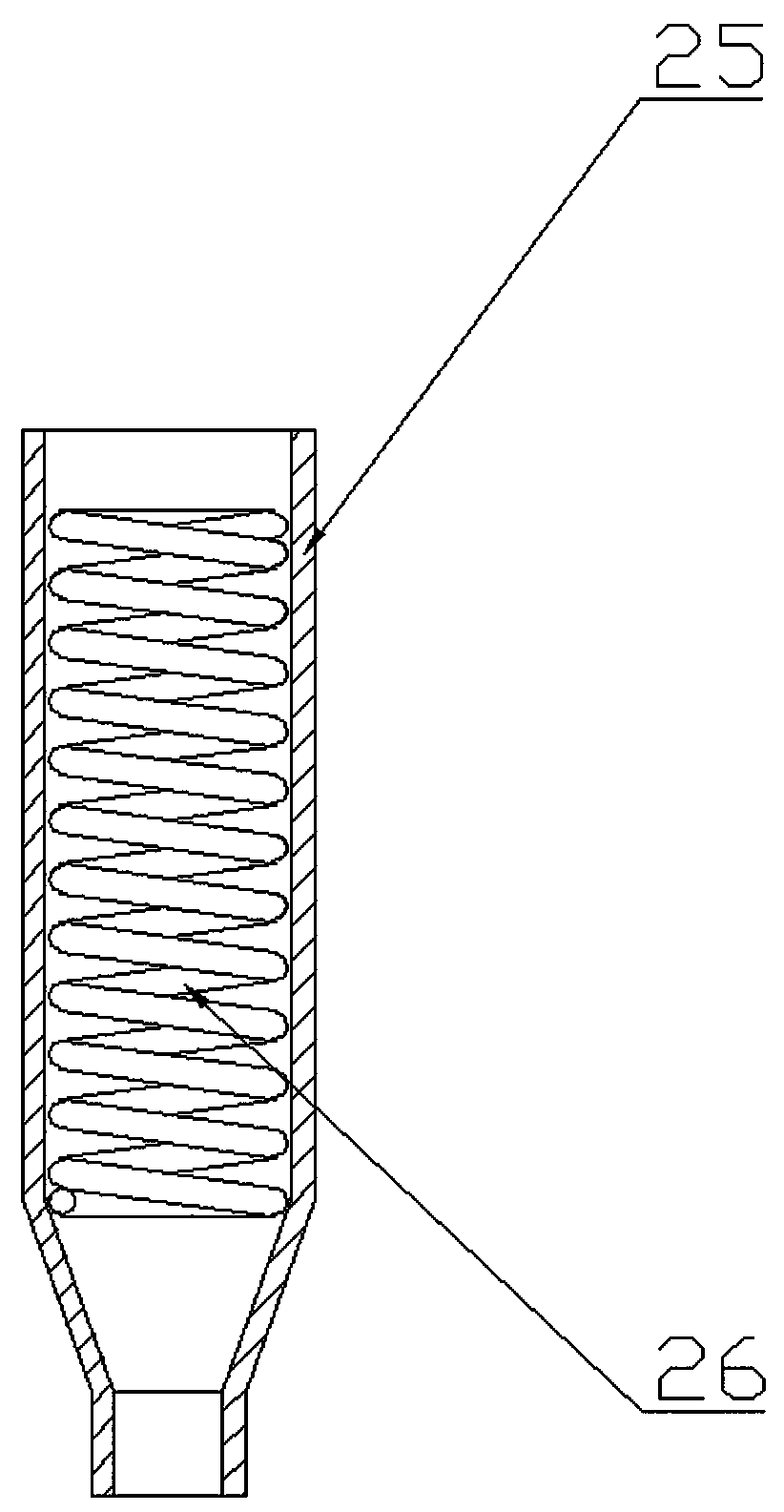
[0028] Example: such as figure 1 and 2 As shown, a vortex separation device includes a liquid storage tank 13, and the liquid storage tank 13 is provided with an infusion pump 4 that is flanged to communicate with the infusion tube 8 and is fixed. The lower end of the infusion pump 4 extends into the liquid storage tank 13, The lower end of the infusion pump 4 is provided with a liquid suction oil filter 16 which is fixedly threaded and sealed with the infusion pump 4 , and a float type liquid level gauge 12 is arranged between the infusion pump 4 and the liquid inlet pipe 11 . A clean liquid tank 1 is provided on the side of the liquid storage tank 13, and the upper end of the clean liquid tank 1 is provided with a liquid supply pump 3 that is flange-type connected with the clean liquid tank 1 and extends int...


PUM


Abstract

The invention relates to a vortex separation device and a control method thereof, and belongs to the technical field of solid-liquid separation equipment. The vortex separation device comprises a liquid storage tank; a purified liquid tank is arranged on the side edge of the liquid storage tank; a sewage tank is arranged on the liquid storage tank; a liquid inlet pipe communicating with the liquidstorage tank is arranged on the side edge of the sewage tank; a vortex separator communicating with a pipeline of a the sewage tank is arranged on the sewage tank; an liquid conveying pipe is arranged between the vortex separator and the liquid storage tank; and a liquid outlet pipe is arranged between the vortex separator and the purified liquid tank. The vortex separator comprises a joint connecting frame; a sewage discharging pipe is arranged at the lower end of the joint connecting frame; a separating outer pipe is arranged between the sewage discharging pipe and the joint connecting frame; and a separation inner vortex pipe assembly which is in nested communication with the sewage discharging pipe is arranged in the separation outer tube. The vortex separation device has the advantages that the structure is compact, functions are complete, the cooling effect of a cooling liquid is good, operation is simple and saves energy, energy is saved, environment protection is achieved, useand maintain are convenient, and the service life is long. The cutting fluid recycling efficiency is improved, large storage and space occupation are avoided, and production cost and cutting fluid consumption and waste are reduced.

Description

technical field [0001] The invention relates to the technical field of solid-liquid separation equipment, in particular to a vortex separation device and a control method thereof. Background technique [0002] The cutting fluid used in machine tools is generally known to have two functions, one is cooling and the other is lubrication. But in the process of lathe processing, another benefit of using cutting fluid is to effectively remove chips, which also helps to extend tool life. If the cutting nozzle is properly placed, it can prevent the chip flutes of milling cutters and drills from being blocked by chips or from poor chip removal. For the processing of some large workpieces, or the powerful cutting and grinding of large feed, two or more rows of coolant nozzles are used to fully cool them, which is conducive to improving processing efficiency and ensuring processing quality. [0003] Cutting fluid is an aqueous solution of oil after emulsification, and is generally re...

Claims


Application Information

Patent Timeline
Patent Type & Authority Applications(China)
IPC IPC(8): B01D36/04
Inventor 沈江湧雷声董林强
Owner 浙江吉宝智能装备股份有限公司
Learn More