Sterilizer heat recovery system

A sterilizer, heat recovery technology, applied in heating, lighting and heating equipment, steam/steam condensers, etc., can solve problems such as affecting the facility environment and difficulty in discharge, and achieve the effect of improving work efficiency and reducing heat loss

Active Publication Date: 2019-06-11
JILIN UNIV +1
View PDF5 Cites 7 Cited by
  • Summary
  • Abstract
  • Description
  • Claims
  • Application Information

AI Technical Summary

Problems solved by technology

[0003] Currently, the commonly used pulsating double-door high-pressure steam sterilizer produces and discharges a large amount of waste steam and high-temperature waste water with a temperature as high as 80-120 ℃, which makes it difficult to discharge. and seriously affect the environment around the facility

Method used


Image

  • Sterilizer heat recovery system
  • Sterilizer heat recovery system
  • Sterilizer heat recovery system

Examples


Embodiment 1

[0066] The raw material formula of the heat insulation layer includes: 25% water-based polyurethane resin, 15% polytetrafluoroethylene, 13% sodium methylene dinaphthalene sulfonate, 5% glycol ether, 3% silicone acrylic emulsion, 7% styrene acrylic emulsion, Silicon carbide 3%, diatomaceous earth 7%, polysiloxane prepolymer 3%, benzophenone 7%, leveling agent 2%, defoamer 2%, dispersant 3%, thickener 2% , Stabilizer 3%. Add the above heat insulation layer raw materials into a strong mixer and stir for 5 minutes to obtain the desired heat insulation layer material.

Embodiment 2

[0068] The raw material formula of the heat insulation layer includes: 30% water-based polyurethane resin, 20% polytetrafluoroethylene, 10% sodium methylene dinaphthalene sulfonate, 8% glycol ether, 5% silicone acrylic emulsion, 5% styrene acrylic emulsion, Silicon carbide 5%, diatomaceous earth 5%, polysiloxane prepolymer 2%, benzophenone 5%, leveling agent 1%, defoamer 1%, dispersant 1%, thickener 1% , Stabilizer 1%. Add the above-mentioned anti-wear layer raw materials into a strong mixer and stir for 8 minutes to obtain the required heat insulation layer material.

[0069] The heat insulation layer materials of Embodiment 1 and Embodiment 2 were attached to the outer layer of the heat preservation water tank 5 respectively, and then the water temperature variation in the heat preservation water tank 5 was measured within 12 hours as shown in Table 3 (under shutdown state).

[0070] 【table 3】

[0071]


PUM


Abstract

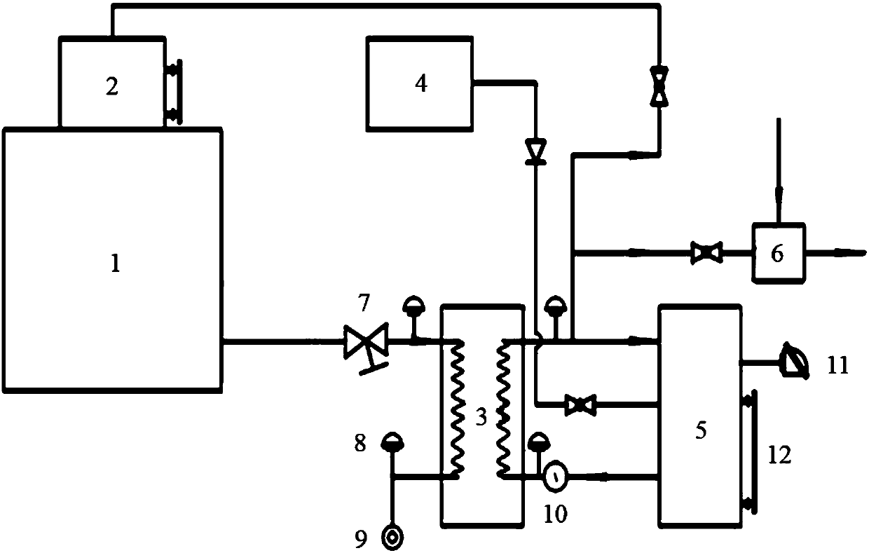
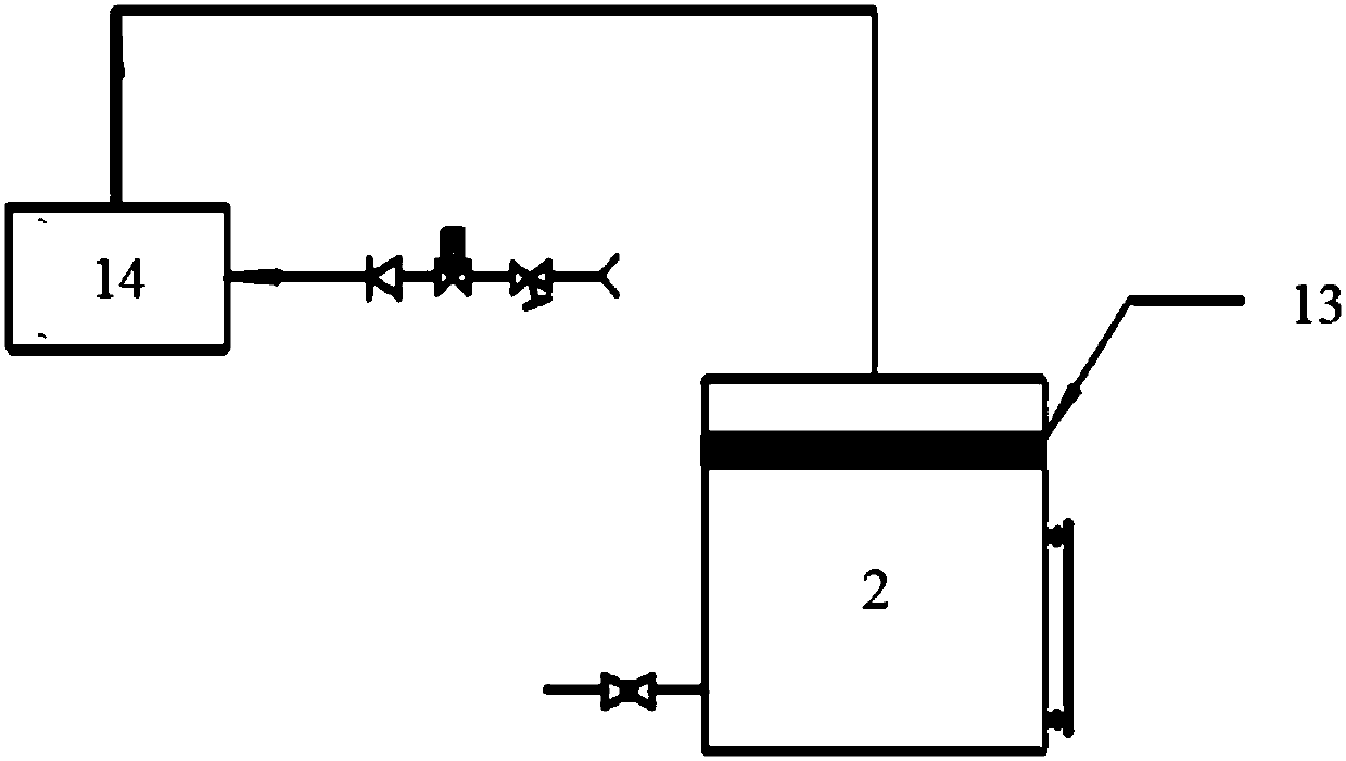
The invention relates to the technical field of heat recovery systems, and in particular to a sterilizer heat recovery system. The sterilizer heat recovery system comprises a sterilizer, a vapor generator, a heat exchanger, an insulating water tank and a water mixer, wherein the heat exchanger comprises a cold fluid inlet, a cold fluid outlet, a hot fluid inlet and a hot fluid outlet; the cold fluid inlet communicates with the cold fluid outlet through a cold flowing pipe in the heat exchanger; the hot fluid inlet communicates with the hot fluid outlet through a hot flowing pipe in the heat exchanger; and the hot fluid inlet communicates with a waste vapor outlet. According to the sterilizer heat recovery system disclosed by the invention, after the sterilizer is sterilized, the obtained waste vapor enters the heat exchanger for heat exchanging; after the heat exchanging of waste vapor is performed, the obtained waste water is discharged into a sewage, the hot water obtained through heat exchanging is supplied to the vapor generator or is used for daily washing, brushing or bathing after passing through the water mixer; on one side, the problems of air pollution and discharging ofhigh-temperature waste water and waste vapor generated by the discharging of high-temperature gas are solved, and on the other side, through heat exchanging, the recovery of heat quantity is realized,and the purposes of saving energy and reducing emission are realized.

Description

technical field [0001] The invention relates to the technical field of heat recovery systems, in particular to a heat recovery system for a sterilizer. Background technique [0002] Microorganisms widely exist in the surrounding environment, and some of them are pathogenic microorganisms. From the perspective of infection prevention, medical workers must strictly implement aseptic operations, and disinfect and sterilize the used items and working environment to ensure the normal progress of medical treatment and scientific research. Disinfection and sterilization are mainly through physical and chemical factors to hinder the main metabolism of microorganisms, or denature and solidify bacterial proteins, or destroy their genetic material, resulting in the death of microorganisms. [0003] At present, the commonly used pulsating double-door high-pressure steam sterilizer produces and discharges a large amount of waste steam and high-temperature waste water with a temperature a...

Claims


Application Information

Patent Timeline
Patent Type & Authority Applications(China)
IPC IPC(8): A61L2/07A61L2/26F28B1/02
Inventor 张大维甘振威孙冰雪王德利房友建
Owner JILIN UNIV
Why Eureka
Try Eureka