
Internet of things based electronic communication cabinet

A technology for communication cabinets and the Internet of Things, which is applied in the direction of cleaning methods using tools, cooling/ventilation/heating transformation, cleaning methods using gas flow, etc., which can solve the inconvenience of transportation of communication cabinets, damage to internal components of communication cabinets, and insufficient Meet the needs of heat dissipation and other issues, and achieve the effects of suitable promotion and use, improved heat dissipation effect, and reasonable design

Inactive Publication Date: 2019-06-07
JINGCHU UNIV OF TECH
View PDF13 Cites 20 Cited by
  • Summary
  • Abstract
  • Description
  • Claims
  • Application Information

AI Technical Summary

Problems solved by technology

[0002] The communication cabinet is made of metal or non-metallic materials, does not allow unauthorized operators to enter the cabinet, and provides physical working environment and security system equipment for wireless communication sites or wired network site workstations, but the existing communication cabinets There are certain defects in use, the transportation of the communication cabinet is inconvenient, and the internal temperature of the communication cabinet is too high, which may easily cause damage to the internal components of the communication cabinet, which has a certain impact on the use process. Therefore, the communication cabinet is now improved.
[0003] Chinese patent (publication number: CN208128744U) discloses an electronic communication cabinet based on the Internet of Things, including a housing, a first fan is installed on the upper surface of the inner wall of the housing, the first fan includes a rotating part, and the rotating part A fan blade is fixed on the upper part of one end of the housing, a power supply box is installed on the rear surface of the inner wall of the housing, a temperature sensor and a temperature controller are installed on the inner left wall of the housing, a fixed base is provided at the lower end of the housing, and A second fan is installed inside the fixed base, a dust-proof vent is provided under the second fan, a control panel and a door are provided at the front end of the housing, and a whirlwind heat dissipation vent is provided on the upper surface of the housing , the device is only equipped with two upper and lower cooling fans, because a lot of communication equipment is placed inside the communication cabinet, and the arrangement is tight, only relying on two cooling fans is not enough to meet the heat dissipation requirements

Method used


Image

  • Internet of things based electronic communication cabinet
  • Internet of things based electronic communication cabinet
  • Internet of things based electronic communication cabinet

Examples


Embodiment 1

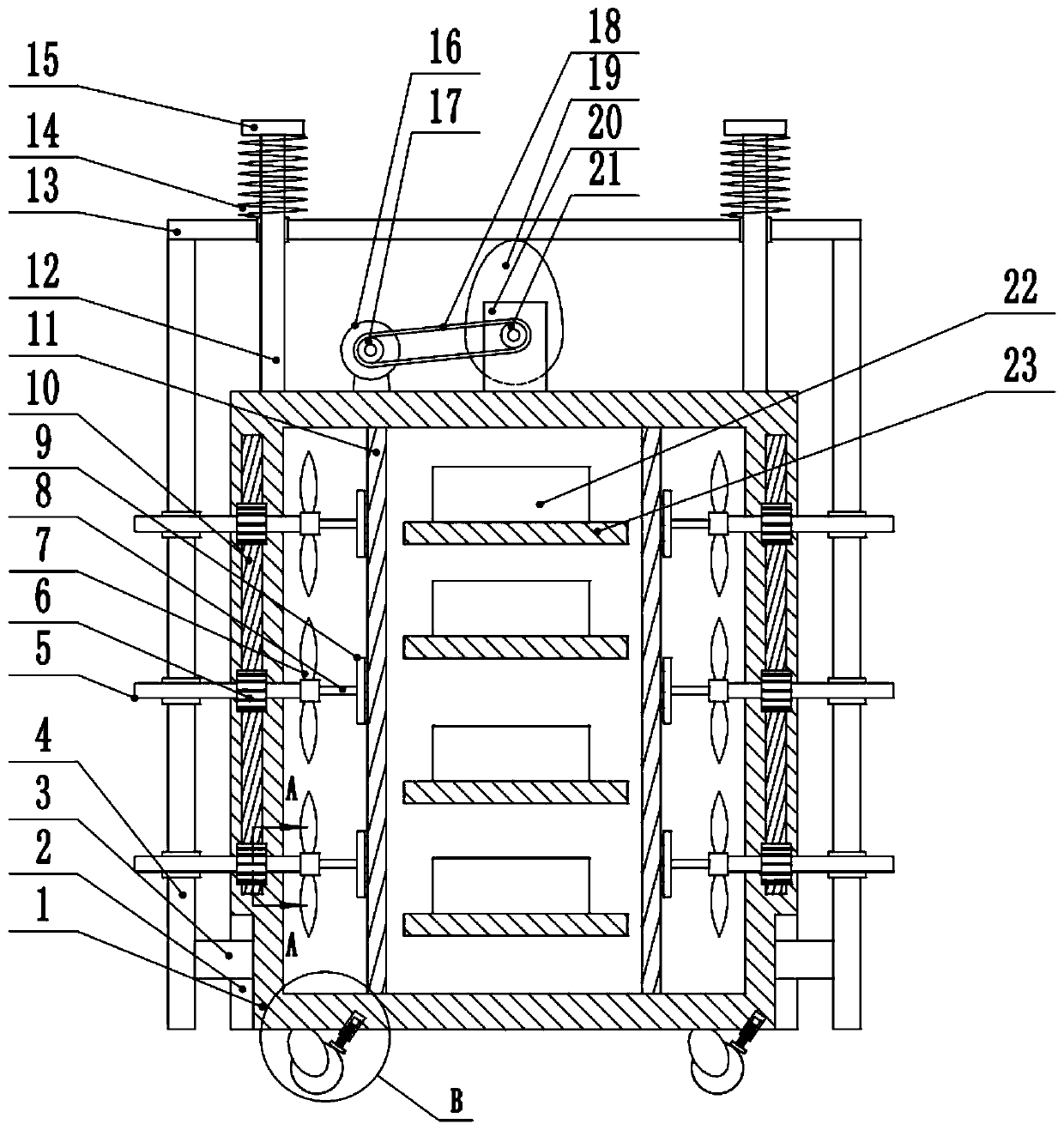
[0025] see figure 1 , an electronic communication cabinet based on the Internet of Things, including a frame 1, chute 2 is provided on the left and right sides of the lower part of the frame 1, and the chute 2 is slidably connected to the slider 3, and the left and right sides of the inside of the frame 1 are provided with dustproof Net 9, the inner wall of the frame 1 is fixedly connected to the storage partition 23, and the communication equipment 22 is placed on the top of the storage partition 23.

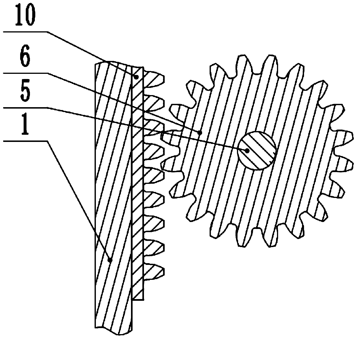
[0026] see Figure 1-4 , the left and right sides of the top of the frame 1 are fixedly connected to the guide column 12, the guide column 12 is slidably connected to the beam 13, the upper part of the guide column 12 is fixedly connected to the limit block 15, the bottom of the limit block 15 is fixedly connected to the spring 14, and the lower end of the spring 14 is fixed Connect the crossbeam 13, the left and right ends of the crossbeam 13 are fixedly connected to the conn...

Embodiment 2

[0028] see figure 1 with 5 , the other content of this embodiment is the same as that of Embodiment 1, the difference is that: the lower part of the frame 1 is fixedly connected to the caster mount 25, the caster mount 25 is rotatably connected to the caster 26, and the upper part of the caster 26 is provided with a top block 28, the top block 28 is fixedly connected to the screw mandrel 27, and the upper end of the screw mandrel 27 is threadedly connected to the bottom of the frame 1. Because some communication cabinets need to move freely, castors 26 are set at the bottom of the frame 1, and top blocks 28 are set on the top of the casters 26. When tight, caster 26 is locked and can't rotate, thereby whole device is fixed.

[0029] In the implementation process of the present invention, the communication equipment 22 is placed on the storage partition 23, the driving motor 16 is started, the output shaft of the driving motor 16 drives the first pulley 17 to rotate, and the ...


PUM


Abstract

The invention relates to the technical field of internet of things electronic communication, and discloses an internet of things based electronic communication cabinet. The cabinet includes a frame; the left and right sides at the lower part of the frame are provided with slide grooves; the slide grooves slidingly connected to slide blocks; the left and right sides at the internal of the frame areprovided with dustproof meshes; the inner wall of the frame is fixedly connected to object placing separating plates; communication equipment is placed on the object placing separating plates; the left and right sides on the top of the frame are fixedly connected to guiding columns; the guiding columns are slidingly connected to a crossbeam; and the left and right ends of the crossbeam are fixedly connected to connecting rods. Through the arrangement of a rack and pinion mechanism consisting of gears and racks, fans and dedusting frames can be driven to rotate through the mechanism, so that the purpose of performing heat dissipation and dedusting on the internal of the cabinet can be realized; the device is simple in operation; through the arrangement of a self-cleaning device, heat dissipation can be performed on the internal of the frame, and surface dust can be removed as well, so that heat dissipation effects can be enhanced; and the cabinet is reasonable in design and suitable for popularization and usage.

Description

technical field [0001] The invention relates to the technical field of Internet of Things electronic communication, in particular to an electronic communication cabinet based on the Internet of Things. Background technique [0002] The communication cabinet is made of metal or non-metallic materials, does not allow unauthorized operators to enter the cabinet, and provides physical working environment and security system equipment for wireless communication sites or wired network site workstations, but the existing communication cabinets There are certain defects in use, the transportation of the communication cabinet is inconvenient, and the internal temperature of the communication cabinet is too high, which may easily cause damage to the internal components of the communication cabinet, which has a certain impact on the use process. Therefore, the communication cabinet is now improved. . [0003] Chinese patent (publication number: CN208128744U) discloses an electronic co...

Claims


Application Information

Patent Timeline
IPC IPC(8): H05K7/20B08B1/00B08B1/04B08B5/02
Inventor 王金翔
Owner JINGCHU UNIV OF TECH
Learn More