
Dynamic Comparator and Electronics

A technology of dynamic comparators and latches, applied in multiple input and output pulse circuits, etc., can solve the problems of small kickback noise and power consumption, achieve small signal gain gain, improve suppression ability, and reduce kickback noise Effect

Active Publication Date: 2022-03-29
NO 24 RES INST OF CETC
View PDF7 Cites 0 Cited by
  • Summary
  • Abstract
  • Description
  • Claims
  • Application Information

AI Technical Summary

Problems solved by technology

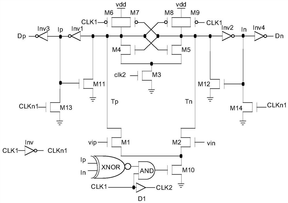
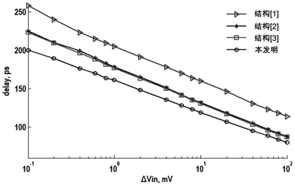
[0004] In view of the above-mentioned shortcomings of the prior art, the purpose of the present invention is to provide a dynamic comparator, which is used to solve the problem that the dynamic comparator in the prior art cannot guarantee less kickback noise and power consumption at a high comparison speed. question

Method used


Image

  • Dynamic Comparator and Electronics
  • Dynamic Comparator and Electronics
  • Dynamic Comparator and Electronics

Examples


Embodiment Construction

[0018] Embodiments of the present invention are described below through specific examples, and those skilled in the art can easily understand other advantages and effects of the present invention from the content disclosed in this specification. The present invention can also be implemented or applied through other different specific implementation modes, and various modifications or changes can be made to the details in this specification based on different viewpoints and applications without departing from the spirit of the present invention. It should be noted that, in the case of no conflict, the following embodiments and features in the embodiments can be combined with each other.

[0019] It should be noted that the diagrams provided in the following embodiments are only schematically illustrating the basic ideas of the present invention, and only the components related to the present invention are shown in the diagrams rather than the number, shape and shape of the compo...


PUM


Abstract

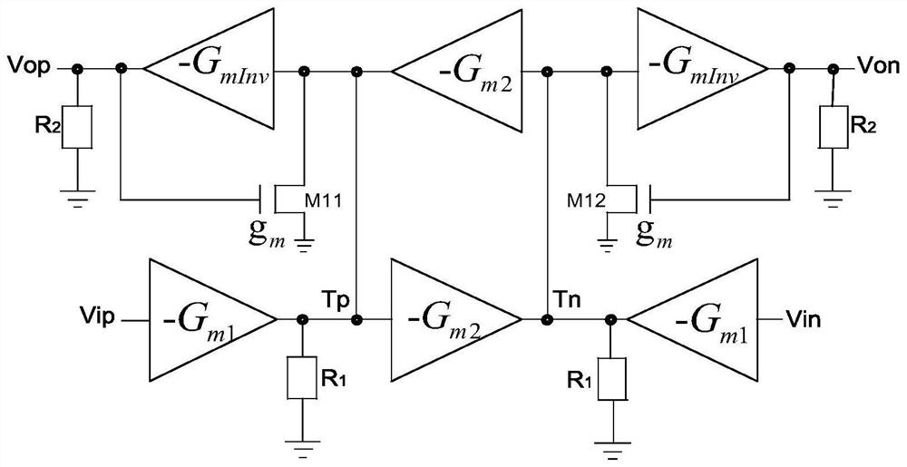
The present invention provides a dynamic comparator, comprising: a clock signal module for generating a first clock signal, a second clock signal and a third clock signal; a positive feedback channel connected to a pre-amplifier and a positive feedback latch respectively, when the first When the three clock signals are at low level, the voltage difference between the two node voltages Tp and Tn connected between the pre-amplifier and the positive feedback latch is raised; when the first and second clock signals are at low level, the node voltage Tp and Tn are pulled up to the power supply voltage to enter the reset state and output high level, which is obtained as low level Ip and In feedback control pre-amplifier after inversion processing; when the first clock signal is high level, the second clock signal is still It is low level, the pre-amplifier is in the working state to amplify the input signal and output the node voltage Tp and Tn with voltage difference, when the second clock signal becomes high level, the voltage difference between the node voltage Tp and Tn makes the positive feedback latch The device enters the latch state and completes the comparison work to output voltage signals Dp and Dn.

Description

technical field [0001] The invention belongs to the technical field of analog or digital-analog mixed integrated circuits, in particular to a high-speed low-kickback noise dynamic comparator and electronic equipment. Background technique [0002] In recent years, with the continuous development of integrated circuit manufacturing technology, the feature size of CMOS devices has been continuously reduced, and the operating voltage of integrated circuits has also been continuously reduced. Under the deep submicron process, the working speed of analog-to-digital converters has been greatly improved. Improve, at the same time, power consumption is further reduced. However, as the core component of the analog-to-digital converter, the performance of the comparator has become a bottleneck in the design of high-speed and low-power consumption. Several traditional comparator structures are difficult to meet the requirements of speed, power consumption, low power supply voltage and ...

Claims


Application Information

Patent Timeline
Patent Type & Authority Patents(China)
IPC IPC(8): H03K5/24
Inventor 徐代果蒋和全于晓权徐世六李儒章王健安陈光炳王育新付东兵
Owner NO 24 RES INST OF CETC
Learn More