
Phase fringe-based code phase measurement method

A measurement method and code phase technology, applied in the field of satellite positioning, to achieve the effect of improving measurement accuracy, low-cost frequency, and wide application value

Active Publication Date: 2019-06-07
NAT ASTRONOMICAL OBSERVATORIES CHINESE ACAD OF SCI
View PDF11 Cites 0 Cited by
  • Summary
  • Abstract
  • Description
  • Claims
  • Application Information

AI Technical Summary

Problems solved by technology

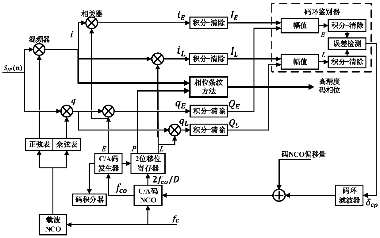
[0007] Although scholars at home and abroad have given a variety of methods to improve the accuracy of the code tracking loop in the above references, the above methods are all based on the correlation function and correlation peak of the two signals, and two or more channels of copy code signals are required Correlation calculations have certain limitations

Method used


Image

  • Phase fringe-based code phase measurement method
  • Phase fringe-based code phase measurement method
  • Phase fringe-based code phase measurement method

Examples


Embodiment Construction

[0053] Before describing the method of the present invention in detail, the principle of the phase fringe method will be described first.

[0054] The phase fringe method in radar technology is often used to measure the time delay of the same signal arriving at two correlated receivers after being reflected. The two signals are denoted as f 1 (t) and f 2 (t), where f 2 (t) = f 1 (t-τ), where τ is the time delay of the signal arriving at the two receivers. Carry out cross-correlation calculation on the two signals, set but Then, the cross-power spectral density of the two signals is:

[0055]

[0056] where R 12 (t) is f 1 (t) and f 2 (t) cross-correlation function. Therefore, the phase of the cross-spectral density is:

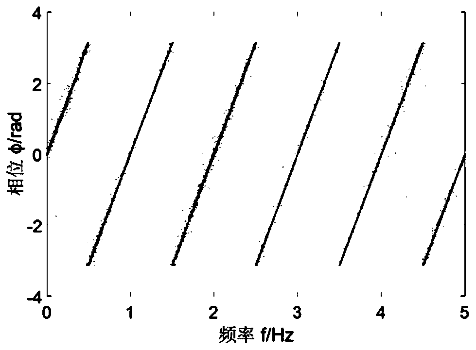
[0057] φ=ωτ=2πτ·f (2)

[0058] It can be seen from formula (2) that when the time delay τ is constant, there is a linear relationship between the phase φ of the cross power spectrum of the two signals and the frequency f, and the slope is only...


PUM


Abstract

The invention discloses a phase fringe-based code phase measurement method. The method includes the following steps that: intermediate-frequency signals down-converted by a receiver radio frequency front end and the local duplication carrier waves and local duplication codes which are obtained after a tracking loop enters a stable tracking state are selected; carrier wave filtering and Doppler frequency shift are performed on the intermediate-frequency signals and the local duplication carrier waves, so that received input signals are obtained; the local duplication codes are adopted as localinput signals; the cross-power spectrum phase of the received input signals and the local input signals is calculated, so that phase fringes are generated; and a fringe frequency is obtained from thephase fringes, so that interval delay between the received input signals and the local input signal is obtained, and therefore, a code phase measurement value is obtained.

Description

technical field [0001] The invention relates to the field of satellite positioning, in particular to a code phase measurement method based on phase fringes. Background technique [0002] Satellite positioning system is a technology that uses satellites to accurately locate objects. It can be used to guide aircraft, ships, vehicles and individuals to follow the selected route safely and accurately to reach the destination on time. Since the United States successfully established the Global Positioning System (GPS) in the 1970s, Europe, Russia, and China have successively launched their own satellite positioning systems, such as Galileo and Beidou. But GPS is still the most widely used satellite positioning system. [0003] The tracking of the navigation signal by the GPS receiver is mainly completed through the carrier loop and the code loop. The tracking loop replicates the carrier and the pseudo code synchronized with the satellite signal, thereby realizing carrier strippi...

Claims


Application Information

Patent Timeline
Patent Type & Authority Applications(China)
IPC IPC(8): G01S19/30
Inventor 王兆瑞傅圣友翟宇霄金声震艾国祥
Owner NAT ASTRONOMICAL OBSERVATORIES CHINESE ACAD OF SCI
Learn More