Electromagnetic reciprocating compressor

A compressor and reciprocating technology, applied in the field of compressors, can solve the problems of affecting the service life of the motor, poor system operation stability, high cost investment, etc., and achieve the effects of small space occupation, stable and reliable operation, and low starting current

Pending Publication Date: 2019-06-07
章宪
View PDF0 Cites 0 Cited by
  • Summary
  • Abstract
  • Description
  • Claims
  • Application Information

AI Technical Summary

Problems solved by technology

[0002] At present, there are many types of compressors, among which various reciprocating compressors are generally classified according to the form of the compressor casing and the setting method of the driving mechanism. Its closed type means that the entire compressor is arranged in one casing. When the compressor starts , the current of the motor will be 4-5 times higher than the rated current, which will not only affect the service life of the motor but also consume more power. In actual products, there will be a certain margin in the selection of the motor, resulting in waste, reciprocating The piston, crank, connecting rod mechanism, slide tube mechanism and other components used in the type compressor are numerous, the failure rate is high, and the system operation stability is poor, resulting in high cost investment in follow-up service of the product, and also brings troubles to users. There is a tendency to be eliminated, and it is urgent to research and design innovative compressors to effectively solve the above problems and bring a novel electromagnetic reciprocating compressor to this huge compressor market to meet market demand.

Method used


Image

  • Electromagnetic reciprocating compressor
  • Electromagnetic reciprocating compressor
  • Electromagnetic reciprocating compressor

Examples


Embodiment Construction

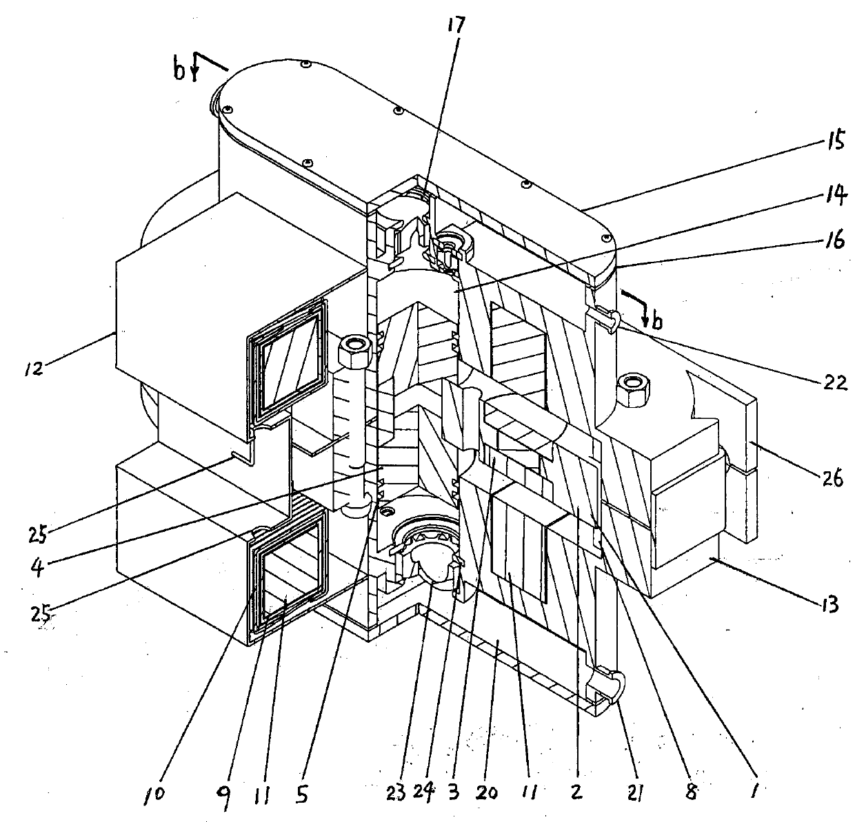
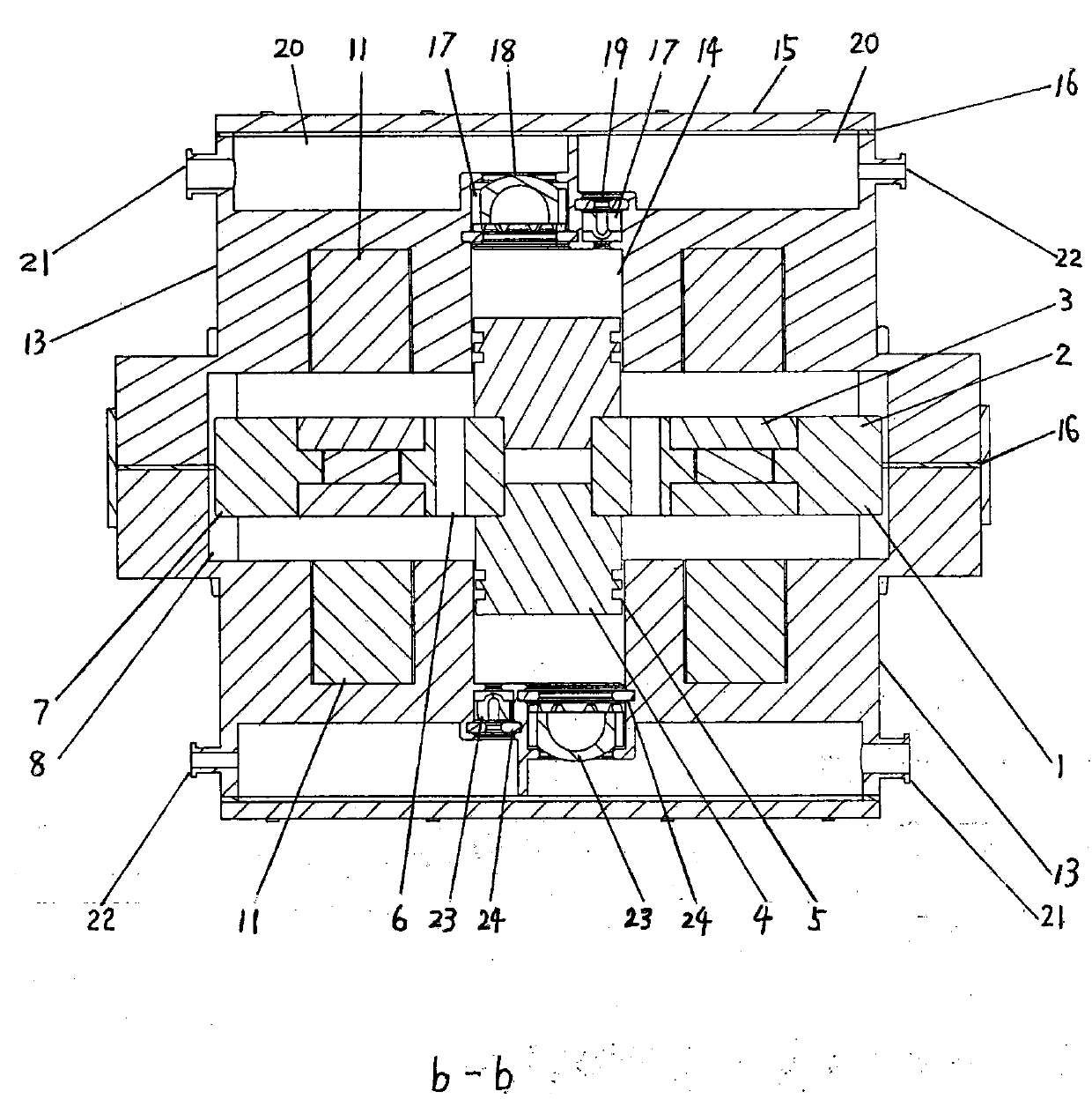
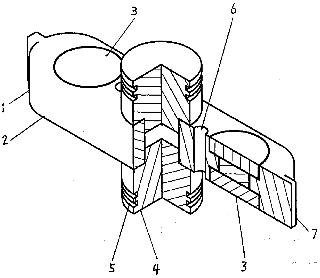
[0018] In the embodiment of the present invention, refer to figure 1As shown in the drawings, the electromagnetic reciprocating compressor, the piston permanent magnet combination slider 1, includes a non-magnetic metal base frame 2, which is usually made of non-magnetic material aluminum alloy or copper alloy, and the base frame 2 is installed on both sides A permanent magnet block 3, or a plurality of permanent magnet blocks 3 are installed on the base frame 2. The permanent magnet is made of rare earth NdFeB strong magnetic material. The permanent magnet block 3 is usually composed of two or three magnets connected in series. The permanent magnets on both sides The position of the block 3 corresponds to the position of the silicon steel electromagnetic core 11 on both sides. The magnetic polarity of the permanent magnet blocks 3 on both sides is opposite. There are piston rings 5, and there are chute tongues 7 at both ends of the base frame 2. The chute tongues 7 are instal...


PUM


Abstract

The invention relates to an electromagnetic reciprocating compressor. The electromagnetic reciprocating compressor comprises a piston permanent magnet combined sliding block, a piston cylinder, an airinlet and exhaust valve, an air chamber, an air inlet, an air exhaust opening, an electromagnetic coil and silicon steel sheet overlying magnetic core, a compressor shell, a protection cover, a single-phase rectification shunting frequency modulation controller or direct-current controller and a storage battery; a non-rotating mechanism and a non-connecting-rod crank part are achieved, the compressor is free of dead corner, environment-friendly, energy-saving, flexible, low in noise, small in weight, small in occupied space, long in service life, stable and reliable in running, small in temperature difference fluctuation, small in starting current, free of excess large current, wide in adaptation range, capable of achieving the compression process of converting low-pressure state into high-pressure state for gas, liquid, and grease, and suitable for small and medium household air conditioners, refrigerators, small bus air conditioners, air conditioner coats, air conditioner cloaks, air conditioner tents, umbrella type air conditioner covers, pressurizing pumps and the like, and novel intelligent temperature and pressure adjusting related functions of a product are enhanced.

Description

technical field [0001] The invention relates to the technical field of compressors. Background technique [0002] At present, there are many types of compressors, among which various reciprocating compressors are generally classified according to the form of the compressor casing and the setting method of the driving mechanism. Its closed type means that the entire compressor is arranged in one casing. When the compressor starts , the current of the motor will be 4-5 times higher than the rated current, which will not only affect the service life of the motor but also consume more power. In actual products, there will be a certain margin in the selection of the motor, resulting in waste, reciprocating The piston, crank, connecting rod mechanism, slide tube mechanism and other components used in the type compressor are numerous, the failure rate is high, and the system operation stability is poor, resulting in high cost investment in follow-up service of the product, and also...

Claims


Application Information

Patent Timeline
Patent Type & Authority Applications(China)
IPC IPC(8): F04B35/04F04B39/10F04B49/06
CPCF04B35/04F04B39/10F04B49/06
Inventor 章宪朱小燕章文婕
Owner 章宪
Why Eureka
Try Eureka