
Locking mechanism for switch machine

A switch machine and locking technology, which is applied in the field of rail transit, can solve problems that affect the switching stability of the switch machine, the stress state of the switch machine is not good, and affect the locking of the switch machine, so as to improve safety and stability , good stress state and simple structure

Active Publication Date: 2019-06-07
CRSC RESEARCH & DESIGN INSTITUTE GROUP CO LTD +1
View PDF5 Cites 5 Cited by
  • Summary
  • Abstract
  • Description
  • Claims
  • Application Information

AI Technical Summary

Problems solved by technology

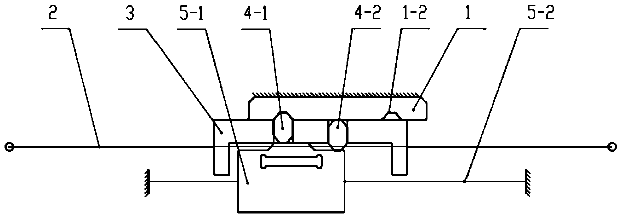
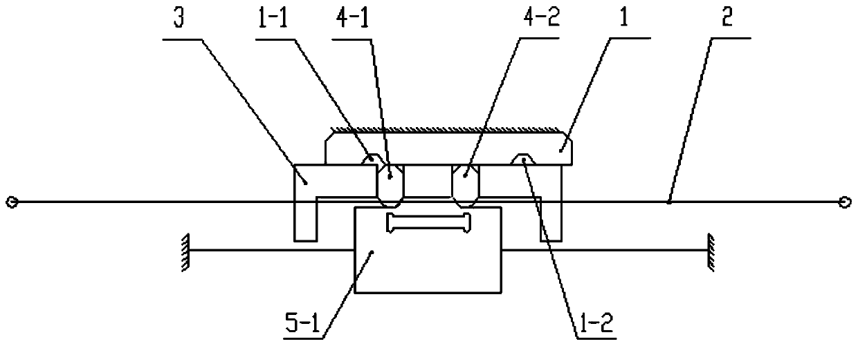
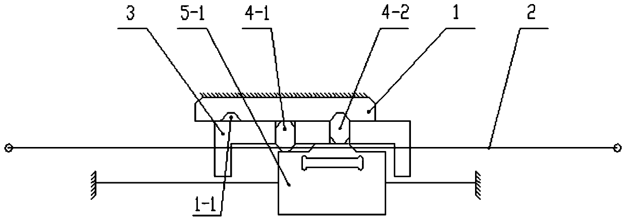
[0003] The locking mechanism is a key component in the switch machine, and the switch machine realizes the locking of the switch through the locking mechanism. The comparative document CN104494647A describes the commonly used locking mechanism of the switch machine in China. In this locking method, the lock block rotates around the pin shaft, and the force between the locking iron, the action rod and the lock block changes continuously during the switchover process of the switch machine, and the force is unbalanced. During the locking process, there will be a gradual increase in locking force, and the stress state during the switching and locking process of the switch machine is not good, which affects the smoothness of the switch machine switching, especially when the operating rod of the switch machine is subjected to external impact , it will affect the locking of the switch by the switch machine

Method used


Image

  • Locking mechanism for switch machine
  • Locking mechanism for switch machine
  • Locking mechanism for switch machine

Examples


Embodiment Construction

[0021] In order to make the purpose, technical solutions and advantages of the embodiments of the present invention more clear, the technical solutions in the embodiments of the present invention will be clearly and completely described below in conjunction with the accompanying drawings in the embodiments of the present invention. Obviously, the described embodiments It is a part of embodiments of the present invention, but not all embodiments. Based on the embodiments of the present invention, all other embodiments obtained by persons of ordinary skill in the art without making creative efforts belong to the protection scope of the present invention.

[0022] Here, a hydraulic switch machine is taken as an example for illustration, but the locking mechanism of the present invention is also applicable to other switch machines.

[0023] The specific working principle of the present invention is: the piston rod composed of the oil cylinder is fixed in the housing, the cylinder ...


PUM


Abstract

The invention discloses a locking mechanism for a switch machine. The locking mechanism for the switch machine comprises locking iron, an action rod, an action block, a lock block group, an oil cylinder assembly and a damping mechanism. Two grooves are formed in one side of the locking iron. Two sliding grooves and two locking blocks which are of a diamond structure are arranged on the action block, and the action rod is fixedly connected with the action block. One side of the action block is in sliding contact with the locking iron, and the other side of the action block is in sliding contactwith an outer cylinder sleeve of the oil cylinder assembly. The damping mechanism is arranged between the locking iron and the outer cylinder sleeve. According to the locking mechanism for the switchmachine, the locking mode of an existing locking mechanism for the switch machine is improved, and the locking stability and reliability are improved.

Description

technical field [0001] The invention belongs to the technical field of rail transit, and in particular relates to a locking mechanism for a switch machine. Background technique [0002] The switch machine is an important railway turnout switching equipment, its function is to switch and lock the turnout, change the opening direction of the turnout, and supervise and check the position of the turnout. The switch machine is an important guarantee to ensure the safety of railway traffic and improve transportation efficiency. [0003] The locking mechanism is a key component in the switch machine. The switch machine realizes the locking of the turnout through the locking mechanism. The reference document CN104494647A describes the commonly used locking mechanism of the switch machine in China. In this locking method, the lock block rotates around the pin shaft, and the force between the locking iron, the action rod and the lock block changes continuously during the switchover p...

Claims


Application Information

Patent Timeline
IPC IPC(8): B61L5/04B61L5/10
CPCB61L5/10B61L5/04
Inventor 杨树仁刘尚超许可证黄天新孙晓勇张玉林薛思忆田爽
Owner CRSC RESEARCH & DESIGN INSTITUTE GROUP CO LTD
Learn More