Eureka AIR delivers breakthrough ideas for toughest innovation challenges, trusted by R&D personnel around the world.

Integrated equipment for efficient treatment of volatile organic waste gas

A volatile organic and waste gas technology, used in air quality improvement, chemical instruments and methods, separation methods, etc., can solve the problems of secondary pollution, poor working conditions, single use of dry filters, etc., to achieve accelerated decomposition, Reliable performance

Pending Publication Date: 2019-06-07
富滇环保科技股份有限公司
View PDF0 Cites 2 Cited by
  • Summary
  • Abstract
  • Description
  • Claims
  • Application Information

AI Technical Summary

Problems solved by technology

Traditional exhaust gas treatment equipment such as UV light oxygen equipment, activated carbon adsorption equipment, dry filters, etc. have some limitations. UV light oxygen equipment technology is mature, but the effect is poor for large air volume and high concentration conditions, and redundant The emission of ozone into the air will cause secondary pollution; activated carbon adsorption equipment requires a large amount of activated carbon, and the replacement cost is high after the activated carbon is saturated, and the saturated activated carbon is troublesome to deal with as hazardous waste: the dry filter has a single purpose and can only remove dust
The efficiency of traditional equipment is low when treating exhaust gas, usually only about 70%, and it is difficult to meet the increasingly stringent national and local emission standards

Method used


Image

  • Integrated equipment for efficient treatment of volatile organic waste gas
  • Integrated equipment for efficient treatment of volatile organic waste gas
  • Integrated equipment for efficient treatment of volatile organic waste gas

Examples


Embodiment Construction

[0022] The following will clearly and completely describe the technical solutions in the embodiments of the present invention with reference to the accompanying drawings in the embodiments of the present invention. Obviously, the described embodiments are only some, not all, embodiments of the present invention. Based on the embodiments of the present invention, all other embodiments obtained by persons of ordinary skill in the art without creative efforts fall within the protection scope of the present invention.

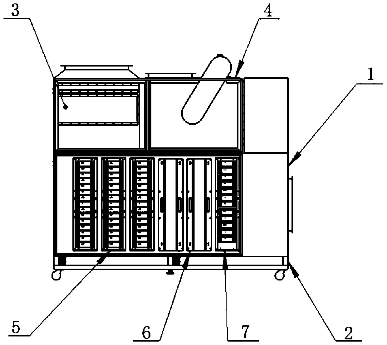
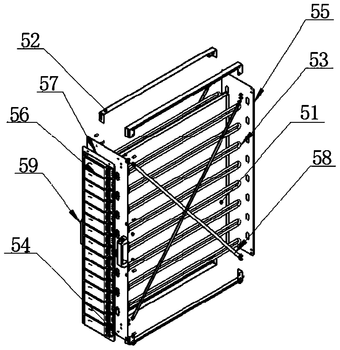
[0023] Such as Figure 1 to Figure 5 The shown embodiment of an integrated device for efficiently treating volatile organic waste gas includes a housing 1 arranged on a base 2, an electric control cabinet is arranged inside the housing 1, and a closed-connected filter module 3 is sequentially arranged inside the housing 1 , UV lamp module 5, activated carbon module 6, deozone module 7 and exhaust module 4, filter module 3 and exhaust module 4 are arranged on the in...


PUM


Abstract

The invention relates to the technical field of environmental protection, in particular to integrated equipment for the efficient treatment of the volatile organic waste gas. The equipment comprises ashell arranged on a base, wherein an electronic control cabinet is arranged in the shell, the interior of the shell is successively provided with a filtering module, a UV lamp module, an activated carbon module, an ozone removal module and an air-pumping module which are connected in a closed manner, the filtering module and the air-pumping module are arranged at the upper part of the interior ofthe shell, the UV lamp module, the activated carbon module and the ozone removal module, which can be disassembled, are arranged at the lower part of the interior of the shell, the upper part of thefiltering module is provided with a waste gas inlet, and the upper part of the air-pumping module is provided with a gas discharge outlet. The external waste gas is subjected to the dust removal by the filtering module, the waste gas decomposition and deodorization by the UV lamp module, the adsorption of the incompletely oxidized organic waste gas by the activated carbon module, the decompositionof the excess ozone by the ozone removal module, and discharge up to standard by the air-pumping module. The equipment integrates dust removal, VOCs waste gas treatment and ozone removal together, and has no secondary pollution and high purification efficiency.

Description

technical field [0001] The patent of the present invention relates to the field of environmental protection technology, in particular to an integrated equipment for efficiently treating volatile organic waste gas. Background technique [0002] With the development of the economy, environmental pollution has become more and more serious, especially the air pollution control is imminent. Under this severe situation, the government has proposed an action plan to win the blue sky defense war. Traditional exhaust gas treatment equipment such as UV light oxygen equipment, activated carbon adsorption equipment, dry filters, etc. have some limitations. UV light oxygen equipment technology is mature, but the effect is poor for large air volume and high concentration conditions, and redundant The emission of ozone into the air will cause secondary pollution; activated carbon adsorption equipment requires a large amount of activated carbon, and the replacement cost of activated carbon ...

Claims


Application Information

Patent Timeline
IPC IPC(8): B01D53/86B01D53/44B01D46/30B01D46/02B01D53/04
CPCY02A50/20
Inventor 夏义珉郭锦雄刘强
Owner 富滇环保科技股份有限公司
Why Eureka
Eureka Blog
Learn More