Power distribution system for optimizing power consumption efficiency of residential area

A technology for power distribution systems and community electricity consumption, which is applied to fixed capacitance components, capacitors, electrical components, etc., can solve the problems of inconvenient reactive power compensation in the community grid, and achieve flexible and changeable size control methods, reduce impact, The effect of easy control

Pending Publication Date: 2019-06-04
YANCHENG INST OF IND TECH
View PDF0 Cites 1 Cited by
  • Summary
  • Abstract
  • Description
  • Claims
  • Application Information

AI Technical Summary

Problems solved by technology

[0005] The purpose of the present invention is to provide a power distribution system that optimizes the power consumption efficiency of the community. By adjusting the parameters of the reactive power compensation capacitor, the size of the cut-in compensation capacitor is adjusted to reduce the voltage impact on the power grid caused by switching. Solved the technical problem of inconvenient reactive power compensation for the residential power grid

Method used


Image

  • Power distribution system for optimizing power consumption efficiency of residential area
  • Power distribution system for optimizing power consumption efficiency of residential area
  • Power distribution system for optimizing power consumption efficiency of residential area

Examples


Embodiment 1

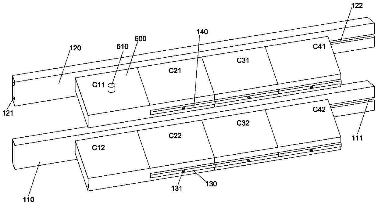
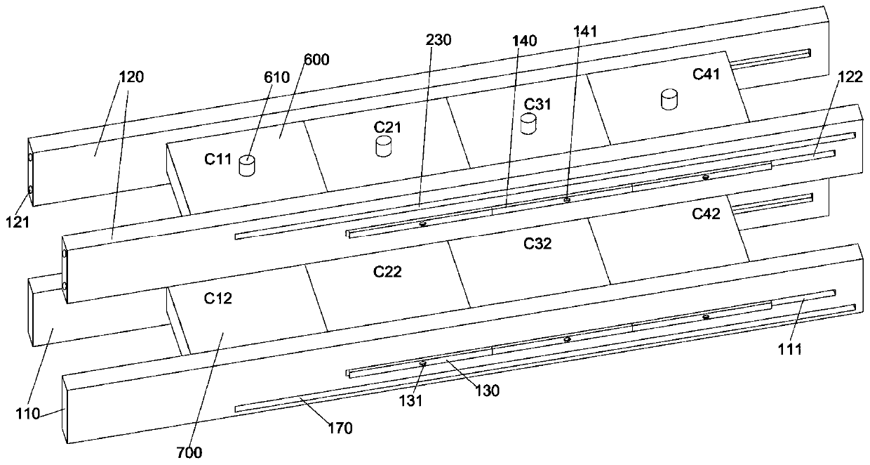
[0034] The first pair of guide rails includes two first guide rails 110 arranged in parallel and spaced apart. Correspondingly, the second pair of guide rails includes two second guide rails 120 arranged in parallel and spaced apart. The first pair of guide rails and the second pair of guide rails are arranged in parallel and spaced apart. In the present invention, the first pair of guide rails and the second pair of guide rails are spaced up and down, and the positions of the first guide rails 110 and the second guide rails 120 correspond to each other.

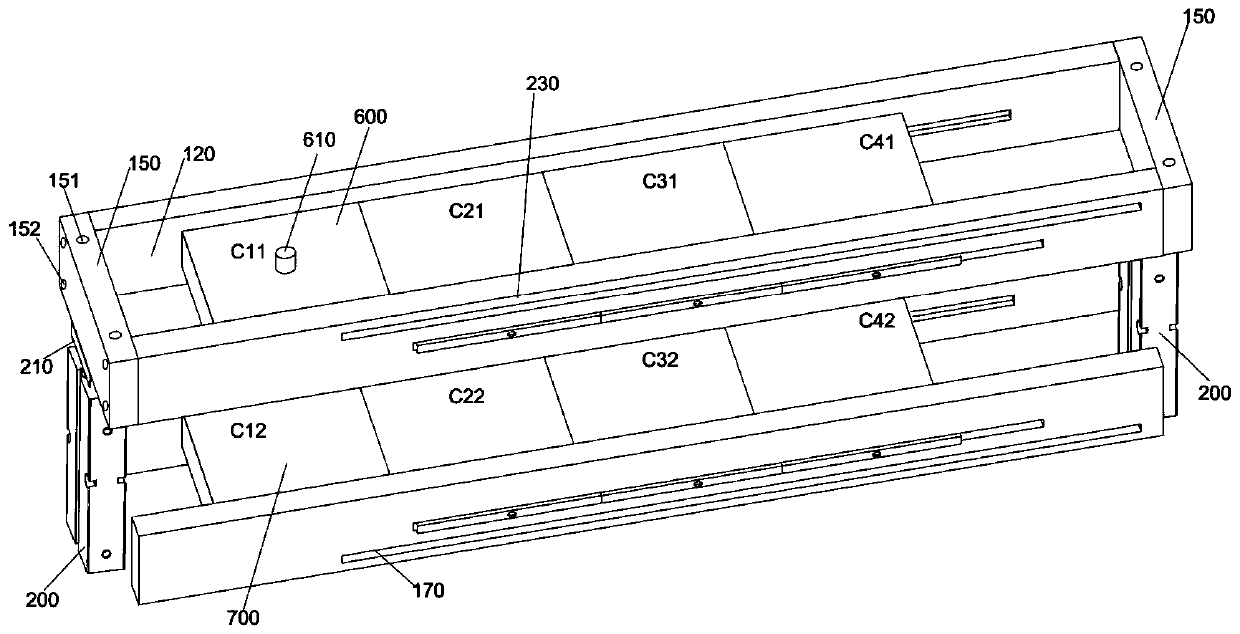
[0035] The positions of the two first guide rails 110 are fixed, but the positions of the second pair of guide rails are not fixed, but move up and down in a direction approaching or away from the first pair of guide rails. A mounting seat 150 is fixed at both ends of the second pair of guide rails. Specifically, the ends of the second guide rail 120 are provided with screw holes 121, and the side walls of the mounting seat 1...


PUM


Abstract

The invention discloses a power distribution system for optimizing the power consumption efficiency of a residential area. A first pair of guide rails includes two first guide rails arranged in parallel and at intervals. A second pair of guide rails includes two second guide rails arranged in parallel and at intervals. The second pair of guide rails moves towards or away from the first pair of guide rails. A first electrode plate is installed between the guide rails in the first pair of guide rails, and the first electrode plate includes several first sub electrode plates. The position of thefirst first sub electrode plate is fixed, and the second to last first sub electrode plates slide between the guide rails in the first pair of guide rails. A second electrode plate is installed between the guide rails in the second pair of guide rails, and the second electrode plate includes several second sub electrode plates. The position of the first second sub electrode plate is fixed, and thesecond to last second sub electrode plates slide between the guide rails in the second pair of guide rails. Each pair of first sub electrode plate and second sub electrode plate at corresponding positions moves synchronously along the lengthwise direction of the guide rails. The technical problem that reactive power compensation for the power grid of a residential area is inconvenient is solved.

Description

technical field [0001] The invention relates to the technical field of smart communities, in particular to a power distribution system for optimizing the power consumption efficiency of a community. Background technique [0002] The daily electricity consumption of community residents is often overloaded, and some old communities have unqualified electrical circuit design, electrical aging, private wires, etc., which increase the probability of electrical fires, indoor paper, foam, etc. Inflammable materials also increase the speed of fire spread. It can be seen that it is necessary to transform the power distribution system of the community to prevent electrical fires. [0003] The power consumption of the community includes a large amount of inductive reactive power, which further increases the burden on the line. In order to reduce the total power consumption and the power consumption burden on each line to a certain extent, a capacitive reactive power switching device ca...

Claims


Application Information

Patent Timeline
Patent Type & Authority Applications(China)
IPC IPC(8): H02J3/18H01G2/02H01G4/228H01G4/38
CPCY02E40/30
Inventor 孙立香武维东单秀文
Owner YANCHENG INST OF IND TECH
Why Eureka
Try Eureka