Measurement method of ultra-high water-cut oil-water holdup based on thermal tracer

A technology of ultra-high water content and measurement method, which is applied in construction and other fields, can solve the problems of large influence on measurement accuracy and complex fluid distribution, and achieve the effects of solving the influence of measurement accuracy, improving measurement accuracy, and stabilizing measurement data

Active Publication Date: 2019-09-24
湖州信倍连网络科技有限公司
View PDF5 Cites 0 Cited by
  • Summary
  • Abstract
  • Description
  • Claims
  • Application Information

AI Technical Summary

Problems solved by technology

[0004] The purpose of the present invention is to provide a method for measuring the ultra-high water-cut oil-water holdup based on thermal tracing. In the water cut period, there is a problem that the fluid distribution is complex and the measurement accuracy is greatly affected

Method used


Image

  • Measurement method of ultra-high water-cut oil-water holdup based on thermal tracer
  • Measurement method of ultra-high water-cut oil-water holdup based on thermal tracer
  • Measurement method of ultra-high water-cut oil-water holdup based on thermal tracer

Examples


specific Embodiment approach 2

[0064] This embodiment is a further description of Embodiment 1. The internal resistance of the heat source generator 4 is R and the heating voltage value U, and the heat Q dissipated when the heat source generator is heated per unit time is calculated. san , whose expression is as follows:

[0065]

[0066] Among them, i is the serial number of the heating voltage, i=1,2,...,n, the expression of the heating voltage vector U of the heat source generator is as follows:

[0067] U={U 1 ,U 2 ,...,U i ,...,U n} T .

specific Embodiment approach 3

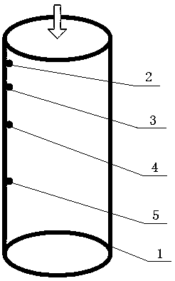
[0069] This embodiment is a further description of Embodiment 2. In step 2, the initial temperature of the water phase and oil phase in the fluid to be measured is detected by the first temperature sensor 3, and the initial temperature value is denoted as T 0 , because the wellbore of the oil well adopts a small pipe diameter, the temperature field of the entire cross-section is regarded as a uniform distribution, and the temperature of the fluid to be measured is detected by the second temperature sensor 5 after heating, and the temperature data of the fluid after heating is recorded as a vector T 1 ,T 1 Expressed as:

[0070] T 1 ={T 11 , T 12 ,...,T 1i ,...,T 1n} T

[0071] Among them, T 1i is the fluid temperature value obtained by the temperature sensor at the i-th heating voltage.

specific Embodiment approach 4

[0073] This embodiment is a further description of Embodiment 3. In step 3, the theoretical value Q of the heat absorbed by the oil phase in the fluid to be measured in the thermal pulse marked after being heated by the heat source generator 4 per unit time is obtained. xio The theoretical value of heat absorbed by the water phase Q xiw , which is expressed as follows:

[0074]

[0075] Among them, q mw is the mass flow rate of water phase per unit time, c w is the specific heat capacity of water, ρ w is the water phase density, q vw is the volumetric flow rate of the water phase;

[0076]

[0077] Among them, q mo is the mass flow rate of oil phase per unit time, c o is the specific heat capacity of oil, ρ o is the oil phase density, q vo is the volumetric flow rate of the oil phase.


PUM


Abstract

The invention relates to method for measuring the water retention rate of extra high water-containing oil based on heat trace. The method for measuring the water retention rate of extra high water-containing oil based on heat trace comprises the steps that heat quantity dissipated during heating of a heat generator in unit time is calculated according to internal resistance and a heating voltage value of the known heat generator; the initial temperature and the temperature after heating in a fluid is measured; the theoretical values of the oil phase heat absorption and the water phase heat absorption in a thermal pulse to-be-tested fluid per unit time are calculated; actual heat quantities absorbed by oil and water are calculated; the sum of volume low rates of each phase fluid per unit time is calculated; measurement models between a heat source heating voltage and the initial temperature, the temperature after heating, a water phase mass flow quantity, and an oil phase mass flow quantity are established; establish a mathematical model of the water phase mass flow quantity and the oil phase mass flow quantity is established; a mathematical model of a water phase holdup rate and anoil phase holdup rate is established. According to the method for measuring the water retention rate of extra high water-containing oil based on heat trace, measurement accuracy is only affected by the sensitivity of a temperature sensor, the influence on the measurement accuracy due to unknown fluid distribution during an extra high water retaining development period is effectively solved, and the measurement accuracy of oil and water holdup rates is improved.

Description

Technical field: [0001] The invention relates to the field of petroleum engineering and measurement, the technology for measuring the oil-water holdup in the wellbore of an oil well, and specifically relates to a method for measuring the oil-water holdup of ultra-high water content based on thermal tracing. Background technique: [0002] Oil holdup and water holdup refer to the volume percentage of oil production and water production in an oil well to the total liquid production within a certain period of time. The accurate measurement of oil-water holdup can not only correct the injection-production plan of the oilfield and measure the oil production of each layer of the oil well, but also reduce the production cost of the oilfield and evaluate the production efficiency of the oilfield. It is an important reference for exploiting onshore oilfields and improving recovery. Scholars at home and abroad have conducted research on holdup measurement. At present, the traditional h...

Claims


Application Information

Patent Timeline
Patent Type & Authority Patents(China)
IPC IPC(8): E21B47/11
Inventor 韩连福王海霞付长凤刘超刘兴斌牟海维谢荣华
Owner 湖州信倍连网络科技有限公司
Why Eureka
Try Eureka