Central coaxial powder feeding type supersonic laser spraying method

A supersonic laser and coaxial powder feeding technology, which is applied in coating, fusion spraying, metal material coating process, etc., can solve the problems of high coating quality, poor process uniformity, lagging laser spraying technology, etc. Good uniformity, reducing the effect of powder splashing

Active Publication Date: 2019-06-04
NAT INNOVATION INST OF DEFENSE TECH PLA ACAD OF MILITARY SCI
View PDF8 Cites 11 Cited by
  • Summary
  • Abstract
  • Description
  • Claims
  • Application Information

AI Technical Summary

Problems solved by technology

[0007] In the early laser spraying technology, the laser beam was almost arranged laterally relative to the spray jet (lateral non-coaxial powder feeding), which severely limited the direction of spray gun movement, and it was difficult to completely overlap the laser spot and the powder deposition spot, resulting in powder Severe spattering and poor process uniformity, resulting in the overall quality of the coating not as high as the cladding layer, which seriously lags behind the development of laser spraying technology

Method used


Image

  • Central coaxial powder feeding type supersonic laser spraying method
  • Central coaxial powder feeding type supersonic laser spraying method
  • Central coaxial powder feeding type supersonic laser spraying method

Examples


Embodiment 1

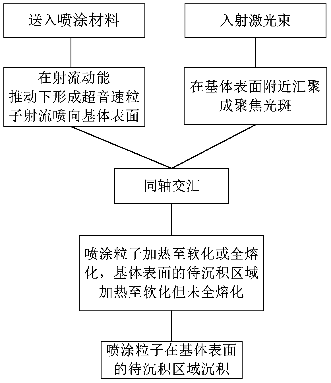
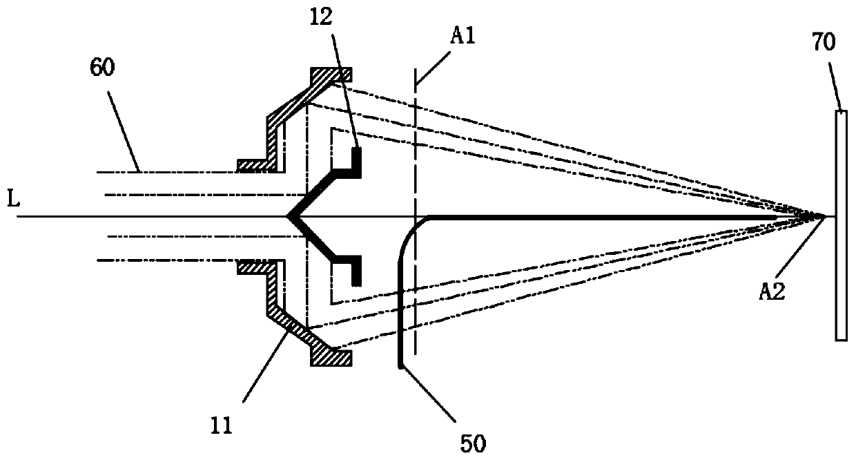
[0065] figure 2 It is shown that a beam of laser 60 is optically transformed through a set of optical lenses, first transformed into several laser beams with gaps between them, and then converged into a ring-shaped focused spot near the surface of the substrate 70, wherein the spraying material 50 It is sent from the gap to the position of the central optical axis L of the laser beam, and then transmitted along the central optical axis L in the hollow area of ​​the laser beam 60 . Specifically, this set of optical lenses includes a beam splitting mirror 12 and a focusing mirror 11 . like figure 2 , a beam of collimated laser is incident from the opening on the focusing mirror 11, and then is transformed into a plurality of reflected beams after hitting the beam splitting mirror 12 to realize beam splitting, and then the reflected beams are directed to the focusing mirror 11 and converted into a convergence beam (see image 3 shown), then a ring-shaped focused spot is form...

Embodiment 2

[0067] Figure 5 It is shown that a beam of laser 60 is optically transformed through a set of optical lenses, firstly transformed into two upper and lower semi-circular annular laser beams with a gap between each other, and then converged into a annular focusing spot near the surface of the base 70, wherein , the spraying material 50 is sent from the gap to the position of the central optical axis L of the laser beam, and then conveyed along the central optical axis L in the hollow area of ​​the laser beam 60 . Specifically, this set of optical lenses includes a collimating lens 21, an axicon lens 22, an upper refracting prism 23, a lower refracting prism 24, a focusing lens 25, and a dust-proof plane mirror 26, which is a dust-proof component of the lens, is also designed. like Figure 5 , a laser beam 60 is injected, and is transformed into a circular parallel collimated laser beam through the collimating lens 21, and then transformed into a circular laser beam through the...

Embodiment 3

[0069] Figure 10 It is shown that each of the six laser beams 60 is optically transformed through a set of optical lenses, and collectively converges into a ring-like focused spot (condensed spot) near the surface of the substrate 70, and each laser beam is 60 degrees circumferentially with the central axis L' Evenly inclined, the spray material 50 is fed directly along the central axis L' and conveyed along the central axis L'. Figure 10 The nozzles 33 arranged along the central axis L' are shown. Specifically, each set of optical lenses includes a collimating lens 31 and a focusing lens 32 . like Figure 10, each of the 6 laser beams is firstly collimated by the collimating lens 31, then focused by the focusing lens 32, and then irradiated to the surface of the substrate 70, and the lasers irradiated to the surface of the substrate 70 completely overlap or partially overlap, and finally form a class near the surface of the substrate. Ring-shaped focus spot, this focus s...


PUM

PropertyMeasurementUnit
Defocus amountaaaaaaaaaa
diameteraaaaaaaaaa

Abstract

The invention discloses a central coaxial powder feeding type supersonic laser spraying method. The central coaxial powder feeding type supersonic laser spraying method comprises the steps that incident one or more laser beams are converged into one or more focusing light spots near the surface of a substrate through optical transformations; spraying materials are input into hollow regions of thelaser beams to be transmitted and form a bunch of supersonic particle jet flow driven by jet flow kinetic energy and the jet flow is sprayed to the surface of the substrate; when the particle jet flowintersects with the coaxial focusing light spots, laser energy is absorbed by sprayed particles and the sprayed particles are heated to soften or melt completely, meanwhile, a part of the laser energy is absorbed by the surface of the substrate, and the surface of the substrate is heated to soften but not melt completely; and a large number of the sprayed particles is subjected to supersonic collision in a to-be-deposited area on the surface of the substrate, and deposition is realized. According to the processes, the particle jet flow and the focusing light spots move continuously together relative to the surface of the substrate, and the sprayed particles deposit and superimpose continuously to form a coating. According to the central coaxial powder feeding type supersonic laser spraying method, by means of a series of the optical transformations, the incident laser beams are transformed and converged into annular or annular-like tiny focusing light spots, and the purpose of the supersonic laser spraying with central coaxial powder feeding is realized.

Description

technical field [0001] The invention relates to a central coaxial powder feeding type supersonic laser spraying method suitable for laser thermal spraying and laser additive manufacturing, and belongs to the technical field of laser spraying. Background technique [0002] Thermal spraying technology is a method that uses a heat source to heat the sprayed material to a fully molten or semi-melted state, and sprays and deposits it on the surface of the pretreated substrate at a certain speed to form a coating. According to the type of heat source of the heating spray material, the thermal spraying technology emerging at present can be divided into: ①flame type, including ordinary flame spraying, explosive spraying, supersonic flame spraying, warm spraying; ②arc type, including arc spraying and plasma spraying;③ Electrothermal method, including electric explosion spraying (also known as electromagnetic accelerated plasma spraying), induction heating spraying, capacitive dischar...

Claims


Application Information

Patent Timeline
Patent Type & Authority Applications(China)
IPC IPC(8): C23C4/123B22F3/105B33Y10/00B33Y30/00
Inventor 陈永雄梁秀兵胡振峰王浩旭张志彬崔辛
Owner NAT INNOVATION INST OF DEFENSE TECH PLA ACAD OF MILITARY SCI
Why Eureka
Try Eureka