Temperature self-adjusting injection punch head

A self-adjusting technology for injection punches, applied in the field of temperature self-adjusting injection punches, can solve the problems of increased friction, scratches, uneven temperature distribution and thermal deformation of injection punches and injection chambers, and achieve saving Cost of use, increased service life, safety and economical advantages

Pending Publication Date: 2019-06-04
GUANGDONG INST OF INTELLIGENT MFG
View PDF0 Cites 0 Cited by
  • Summary
  • Abstract
  • Description
  • Claims
  • Application Information

AI Technical Summary

Problems solved by technology

If the injection punch and the injection chamber are not in the same axis, there will be a lot of friction, which will cause the wear of the injection punch and the injection chamber
However, the injection punch and the injection chamber are in contact with the high-temperature molten metal for a long time, and they will be deformed by heat. The uneven temperature distribution on the injection punch will lead to uneven thermal deformation.
As a result, the roundness of the injection punch will change, which will intensify the friction between the injection punch and the injection chamber, resulting in wear; and it will also cause the local area between the injection punch and the injection chamber to be too small or too large gap, resulting in leakage
The leaked molten metal will cause great friction, scratches or even jamming of the injection punch after cooling, seriously affecting the service life of the injection punch and the injection chamber

Method used


Image

  • Temperature self-adjusting injection punch head
  • Temperature self-adjusting injection punch head
  • Temperature self-adjusting injection punch head

Examples


Embodiment Construction

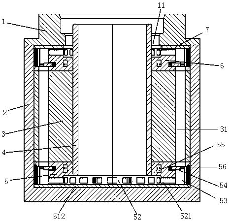
[0026] Such as Figure 1-3 As shown, a temperature self-adjusting injection punch of the present invention includes a punch base 1, a punch shell 2 and a punch body 3 installed on the punch base 1, and the center of the punch base 1 and the punch body 3 A cooling water inlet pipe 4 is provided on the top, and a plurality of cooling branch pipelines 31 are evenly distributed around. There is a water inlet flow regulating mechanism 5 , the punch housing 2 is set on the punch body 3 and the water inlet flow regulating mechanism 5 and is fixedly connected with the punch base 1 .

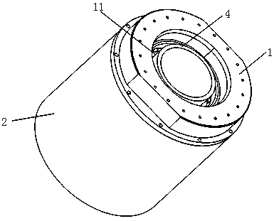
[0027] Such as Figure 4 As shown, the punch base 1 is composed of an interface 11 and a base 12, and the interface 11 and the base 12 have a hole in the center for the cooling water inlet pipe 4 to pass through. The interface 11 has threads 13 for connecting the injection rod; the base 12 has circumferentially uniform threaded holes 14 for installing the beryllium copper shell 2 of the punch.

[0028...


PUM


Abstract

The invention discloses a temperature self-adjusting injection punch head. The temperature self-adjusting injection punch head comprises a punch head base, a punch head shell and a punch head body, acooling water inlet pipe is arranged on the center of the punch head base and the center of the punch head body, a plurality of cooling branch pipelines are uniformly distributed on the periphery of the cooling water inlet pipe, a water outlet cavity communicated with all the cooling branch pipelines is formed in the punch head base, and a water inlet flow adjusting mechanism is arranged on the punch head body; and control switches capable of controlling the flow of each cooling branch pipeline according to the temperature change are arranged in the water inlet flow adjusting mechanism. In theworking state, when the temperature of the temperature self-adjusting injection punch head is unevenly distributed, the pressure of temperature sensing cavities with high temperature is large, the corresponding flow control switches are thus pushed to increase the coolant flow in the control area, and the coolant flow in other cooling areas is reduced through the pressure action of a pressure adjusting cavity, so that the temperature of the punch head is balanced, the circumferential thermal expansion amount of the punch head is kept consistent, the punch head can always maintain good roundness and coaxiality when being matched with and injection chamber, and the service life of the punch head is thus greatly prolonged.

Description

technical field [0001] The invention relates to the technical field of die-casting equipment, in particular to a self-adjusting temperature injection punch. Background technique [0002] At present, die casting machine is a kind of pressure casting equipment. Die casting has the advantages of high dimensional accuracy, fast production speed, good mechanical properties of castings, and smooth surface of castings. It is generally used for large-scale non-ferrous metal casting. During die casting, the temperature of the metal solution can generally reach 500~700°C. The injection punch is a part of the die-casting machine. Its function is to quickly press the high-temperature metal solution in the injection chamber into the mold cavity under the action of the hydraulic push rod, and maintain a certain pressure for a period of time until The casting is finally cooled and formed before entering the next injection cycle. [0003] When the existing injection punch is injected, the...

Claims


Application Information

Patent Timeline
Patent Type & Authority Applications(China)
IPC IPC(8): B22D17/20
Inventor 吴智恒毛璐瑶殷术贵罗良传郭伟科白乃贵
Owner GUANGDONG INST OF INTELLIGENT MFG
Why Eureka
Try Eureka