All-terrain self-balancing taking-off and landing platform for multi-rotor-wing unmanned aerial vehicle

A multi-rotor UAV and take-off and landing platform technology, applied to aircraft parts, ground devices, portable landing gear, etc., can solve the problems of long time-consuming leveling and difficulty in ensuring levelness, so as to reduce output costs and shorten operation time , Improve the efficiency of inspection operations

Active Publication Date: 2019-09-20
CHANGCHUN POWER SUPPLY COMPANY OF STATE GRID JILINSHENG ELECTRIC POWER SUPPLY +1
View PDF6 Cites 6 Cited by
  • Summary
  • Abstract
  • Description
  • Claims
  • Application Information

AI Technical Summary

Problems solved by technology

[0004] The purpose of the present invention is to provide a multi-rotor unmanned aerial vehicle all-terrain self-balancing take-off and landing platform, to solve the existing multi-rotor unmanned aerial vehicle all-terrain self-balancing The take-off and landing platforms are all manually adjusted, which not only takes a long time to level, but also makes it difficult to ensure the levelness

Method used


Image

  • All-terrain self-balancing taking-off and landing platform for multi-rotor-wing unmanned aerial vehicle
  • All-terrain self-balancing taking-off and landing platform for multi-rotor-wing unmanned aerial vehicle
  • All-terrain self-balancing taking-off and landing platform for multi-rotor-wing unmanned aerial vehicle

Examples


Embodiment Construction

[0016] In the following description, for purposes of explanation, numerous specific details are set forth in order to provide a thorough understanding of one or more embodiments. It may be evident, however, that these embodiments may be practiced without these specific details. In other instances, well-known structures and devices are shown in block diagram form in order to facilitate describing one or more embodiments.

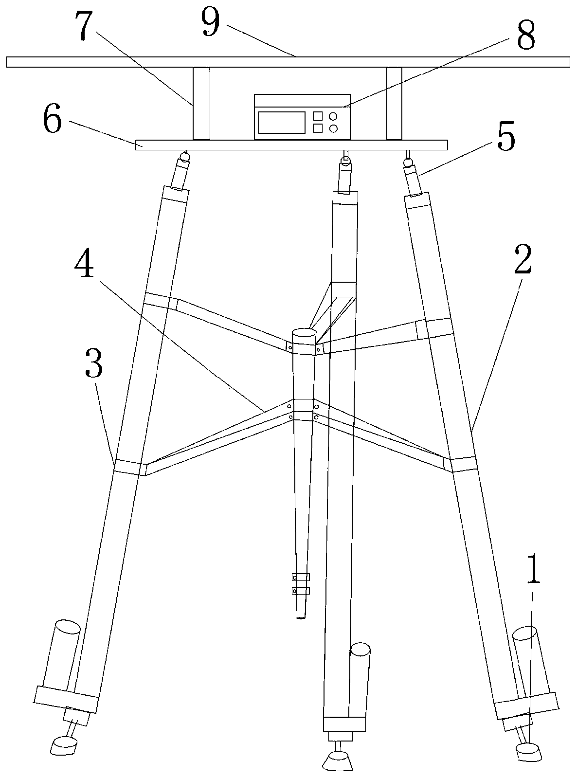
[0017] figure 1 The structure of the multi-rotor UAV all-terrain self-balancing take-off and landing platform provided by the embodiment of the present invention is shown.

[0018] Such as figure 1 As shown, the multi-rotor UAV all-terrain self-balancing take-off and landing platform provided by the present invention includes: universal adjustment feet 1, electric push rod 2, push rod clamp 3, push rod support frame 4, universal joint 5, Support connecting plate 6, table support 7, balance controller 8 and platform table top 9; Wherein, electric push rod 2...


PUM


Abstract

The invention provides an all-terrain self-balancing taking-off and landing platform for a multi-rotor-wing unmanned aerial vehicle. The all-terrain self-balancing taking-off and landing platform comprises three electric push rods, a push rod support bracket, a support linkage plate, a table support, a balance controller and a platform table. Each electric push rod is provided with two push rod hoops. The bottom end of each electric push rod is in threaded connection with a universal adjustment support foot. The top end of each electric push rod is hinged to the bottom face of the support linkage plate through a universal joint. The balance controller is fixed to the top face of the support linkage plate. The platform table is supported above the support linkage plate through the table support. The push rod support bracket comprises a support rod and six connecting arms. The six push rod hoops are hinged to one ends of the six connecting arms correspondingly. The other ends of the six connecting arms are hinged to connecting pieces and the top end of the support rod, wherein the connecting pieces are connected to the support rod in a sleeving manner. By means of the all-terrain self-balancing taking-off and landing platform, self-balancing adjustment of the level degree can be achieved; damage, caused by accidents such as toppling and air crash, to a rotor wing of an unmanned aerial vehicle is avoided; and the maintenance output cost of the unmanned aerial vehicle is lowered.

Description

technical field [0001] The invention belongs to the technical field of unmanned aerial vehicle flight supporting facilities, and in particular relates to a multi-rotor unmanned aerial vehicle all-terrain self-balancing take-off and landing platform. Background technique [0002] State Grid Corporation regards intelligent transportation inspection as the main way to improve the efficiency of transportation inspection under the current situation of high staff shortage rate. Multi-rotor drones have the characteristics of simple structure, flexible maneuverability, hoverability, and low cost of use. They are widely used in intelligent inspection of power transmission lines. However, limited by the battery life of the drone, the task load of the multi-rotor drone is very small, and it needs to take off and land frequently to replace the battery during use, and the power lines are mainly located in fields, steep slopes, mountains, rocks, bushes and weeds In complex environments s...

Claims


Application Information

Patent Timeline
Patent Type & Authority Applications(China)
IPC IPC(8): B64F1/00
CPCB64F1/007
Inventor 苗红松孙峰池澄张爽张益霖
Owner CHANGCHUN POWER SUPPLY COMPANY OF STATE GRID JILINSHENG ELECTRIC POWER SUPPLY
Why Eureka
Try Eureka