Stabilizer

A stabilizer and friction mechanism technology, which is applied to supporting machines, mechanical equipment, machines/stands, etc., can solve the problems of inconvenience to carry, large size of the stabilizer, and inability to achieve balance adjustment for shooting, and achieves easy portability and smaller size. Effect

Active Publication Date: 2021-05-28
SHANGHAI LONGCHEER TECH CO LTD
View PDF13 Cites 0 Cited by
  • Summary
  • Abstract
  • Description
  • Claims
  • Application Information

AI Technical Summary

Problems solved by technology

[0003] The existing stabilizers are mainly mechanical stabilizers without motors and motor stabilizers with motors. The utility model patent with the authorized announcement number CN204908269U discloses an umbrella-type selfie stick, which can stretch and adjust the length of the handle and realize the clamping, but can not achieve the balance adjustment of the shooting; the utility model patent with the authorized announcement number CN 202710908 U discloses a shooting equipment stabilizer, including a bracket, a fixing device, a universal component connector, a universal component, The left and right adjustment devices and counterweights, the bracket includes a horizontal plane for installing the shooting equipment, the shooting equipment is installed on the horizontal plane of the bracket through the fixing device, the horizontal plane of the bracket is also connected to the universal component through the universal component connector, the bracket The lower end is connected to the counterweight through a left and right adjustment device. Although this device can achieve stable adjustment, the process of stable adjustment is very cumbersome, and automatic balance adjustment cannot be realized, and the overall size of the equipment is large and inconvenient to carry; the opening date is 2017 The invention patent application on November 10, 2009 disclosed a stabilizer and a method for adjusting the angle of the stabilizer. Multiple motors are used to realize automatic adjustment, but the stabilizer is large in size and limited by battery power and motor performance. Users need to wait for the response time of the motor during use

Method used


Image

  • Stabilizer
  • Stabilizer
  • Stabilizer

Examples


Embodiment 1

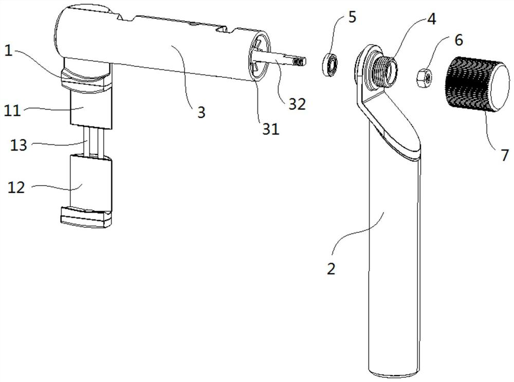
[0054] Such as figure 1 As shown, a stabilizer includes:

[0055] The clamping part 1 is used to clamp the shooting equipment, and the clamping part 1 includes an upper claw 11, a lower claw 12 and a telescopic connector 13, and the telescopic connector 13 is arranged between the upper claw 11 and the lower claw 12 so that The distance between the upper claw 11 and the lower claw 12 can be stretched to adapt to different sizes of shooting equipment. The upper end of the upper claw 11 is connected to one end of the stabilizer body 3 .

[0056] 2 handles, easy to hold.

[0057] A stabilizer body 3 , one end of the stabilizer body 3 is connected to the clip 1 , and the other end is provided with a connecting portion 31 and a rotating shaft 32 .

[0058] A connecting pipe 4 , one end of the connecting pipe 4 is rotatably connected to the connecting portion 31 , and the connecting pipe 4 is connected to the handle 2 .

[0059] The bearing 5 is sleeved between the connecting pipe...

Embodiment 2

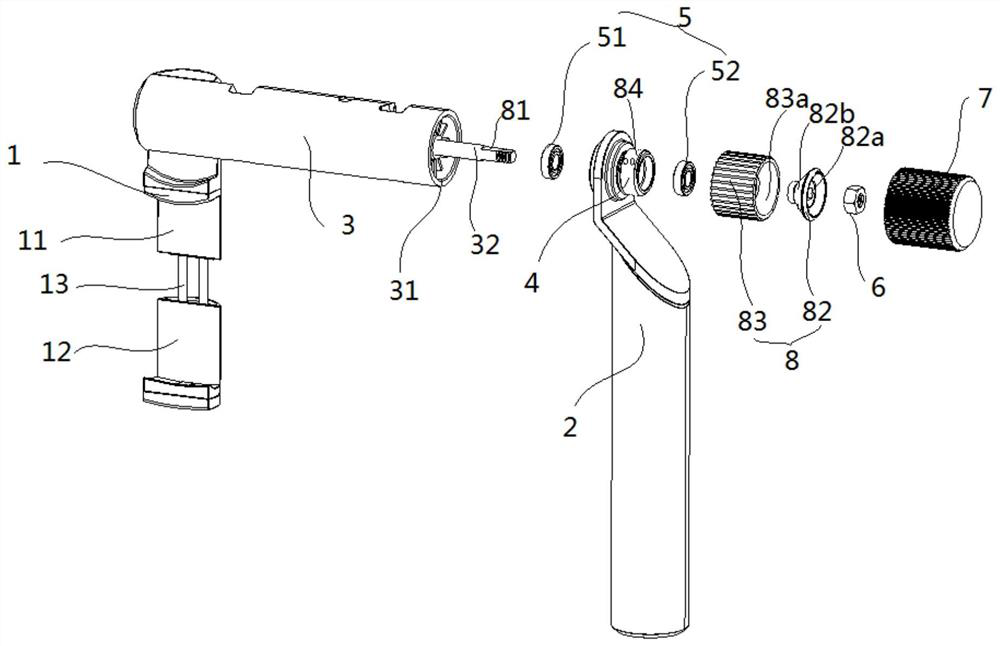
[0064] Such as Figure 2 to Figure 8 As shown, a stabilizer includes:

[0065] Clamping piece 1, used for clamping the shooting equipment, said clamping piece 1 includes upper claw 11, lower claw 12 and telescopic connector 13, said telescopic connector 13 is arranged between upper claw 11 and lower claw 12 The distance between the upper claw 11 and the lower claw 12 can be stretched to adapt to shooting equipment of different sizes. The upper claw 11 is connected to one end of the stabilizer body 3, and the elastic stretchable part can be made of spring or rubber material. Strength rubber band, etc.

[0066] 2 handles, easy to hold.

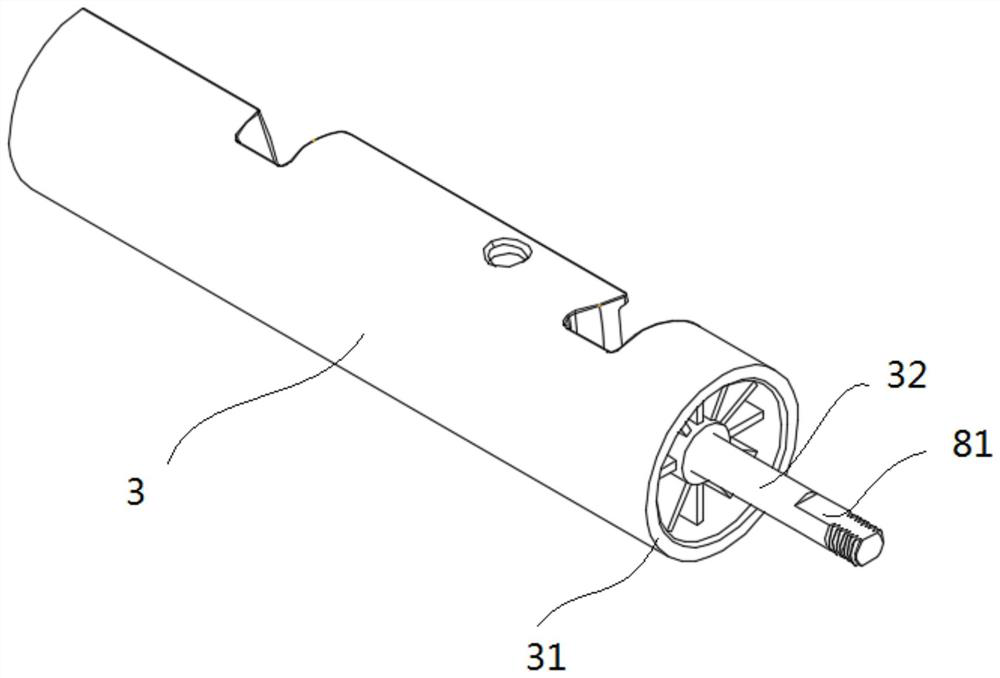
[0067] Stabilizer body 3, such as image 3 As shown, one end of the stabilizer body 3 is fastened to the clip 1 , and the other end is provided with a connecting portion 31 and a rotating shaft 32 .

[0068] connecting pipe 4, such as Figure 4 As shown, one end of the connecting pipe 4 is rotatably connected to the connecting portion 31, a...

Embodiment 3

[0079] Such as Figure 5 , Figure 6 , Figure 9 to Figure 14 As shown, a stabilizer includes:

[0080] Clamping piece 1, used for clamping the shooting equipment, said clamping piece 1 includes upper claw 11, lower claw 12 and telescopic connector 13, said telescopic connector 13 is arranged between upper claw 11 and lower claw 12 The distance between the upper claw 11 and the lower claw 12 can be expanded and contracted to adapt to shooting equipment of different sizes. The upper claw 11 is connected to the stabilizer body 3 through a first rotating connection 14, so that the clamping member 1 and the The stabilizer body 3 can be rotated and locked.

[0081] 2 handles, easy to hold.

[0082] Stabilizer body 3, such as Figure 12 As shown, one end of the stabilizer body 3 is rotatably connected to the clamping piece 1, and the other end is provided with a connecting portion 31 and a rotating shaft 32. The side wall of the stabilizer body 3 is provided with a Combined wi...


PUM


Abstract

The present application provides a stabilizer, including a clamp used to fix the shooting equipment, a handle that is convenient to hold, a stabilizer body, a connecting pipe, a bearing and a stopper, one end of the stabilizer body is connected to the clamp , the other end is provided with a connecting portion and a rotating shaft, one end of the connecting pipe is rotatably connected to the connecting portion, the connecting pipe is connected to the handle, and the sleeve of the bearing is projected between the connecting pipe and the rotating shaft In between, the firmware part is fixedly connected to the end of the rotating shaft, and the bearing is blocked on the inner side of the blocking part. Through the above technical solution, the self-balancing adjustment of the shooting device in the vertical direction can be realized. In addition, By installing a posture fixing mechanism, the shooting equipment can maintain a fixed posture for shooting, and finally, by installing a rotating connecting piece, the folding function of the stabilizer is realized, making it smaller in size and easy to carry.

Description

technical field [0001] The present application relates to the field of photographing equipment, in particular to a stabilizer for assisting photographing. Background technique [0002] The stabilizer is used to fix the target carrier, adjust the posture of the target carrier and keep the target carrier stable at a certain posture, so as to achieve stable, smooth and multi-angle shooting of the target carrier. The target carrier includes but not limited to cameras, mobile phones and camera. [0003] The existing stabilizers are mainly mechanical stabilizers without motors and motor stabilizers with motors. The utility model patent with the authorized announcement number CN204908269U discloses an umbrella-type selfie stick, which can stretch and adjust the length of the handle and realize the clamping, but can not achieve the balance adjustment of the shooting; the utility model patent with the authorized announcement number CN 202710908 U discloses a shooting equipment stabi...

Claims


Application Information

Patent Timeline
Patent Type & Authority Patents(China)
IPC IPC(8): F16M13/04F16M11/04F16M11/10
CPCF16M11/04F16M11/10F16M13/04
Inventor 鲁伟廖敏希萧建伟杜军红汤肖迅
Owner SHANGHAI LONGCHEER TECH CO LTD
Why Eureka
Try Eureka