Special photooxygen catalytic device for waste gas treatment

A photo-oxygen catalytic device and exhaust gas treatment technology, applied in chemical instruments and methods, dispersed particle separation, separation methods, etc., can solve the problems of inconvenient installation and disassembly of the turntable, adjustment of the distance between the lamp tube and the turntable, and poor quality of exhaust gas. Achieve the effects of oxidation, deodorization and sterilization, ensuring flexibility and uniform distribution

Inactive Publication Date: 2019-06-04
苏州弘维环境科技有限公司
View PDF7 Cites 2 Cited by
  • Summary
  • Abstract
  • Description
  • Claims
  • Application Information

AI Technical Summary

Problems solved by technology

[0004] The purpose of the present invention is to solve the low efficiency of the existing photo-oxygen catalytic device for photo-oxygen catalytic treatment of exhaust gas, and the range of UV ultraviolet rays irradiated by the lamp tube to exhaust gas is relatively small, resulting in insufficient comprehensive and thorough photo-oxygen catalytic treatment of exhaust gas. Moreover, the photo-oxygen catalytic device cannot adjust the distance between the lamp tube and the turntable according to the type of exhaust gas to be catalyzed, resulting in poor quality of different types of exhaust gas being treated, and the device can be adjusted poorly. The turntable in the device is installed 1. The disassembly is not convenient enough, and the staff cannot flexibly adjust the working position and angle of the catalytic box 2, which makes it difficult for the exhaust gas to pass into the catalytic box and is easy to be blocked when passing through the exhaust gas, which affects the efficiency of the exhaust gas being catalyzed by photo-oxygen. A special photo-oxygen catalytic device for waste gas treatment

Method used


Image

  • Special photooxygen catalytic device for waste gas treatment
  • Special photooxygen catalytic device for waste gas treatment
  • Special photooxygen catalytic device for waste gas treatment

Examples


Embodiment Construction

[0049] The technical solutions of the present invention will be clearly and completely described below in conjunction with the embodiments. Apparently, the described embodiments are only some of the embodiments of the present invention, not all of them. Based on the embodiments of the present invention, all other embodiments obtained by persons of ordinary skill in the art without creative efforts fall within the protection scope of the present invention.

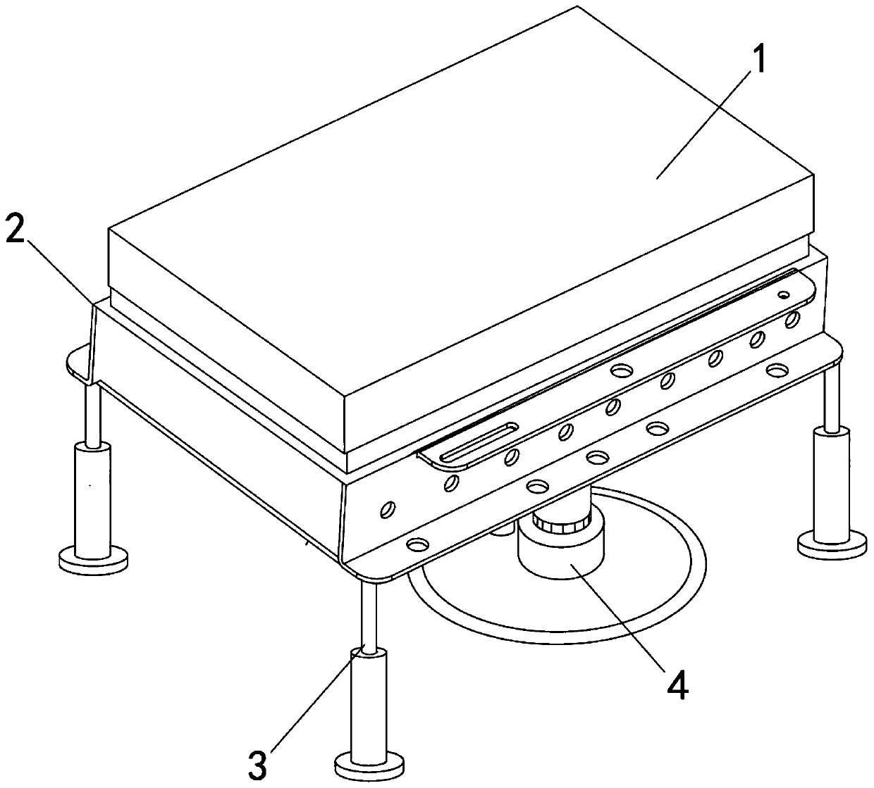
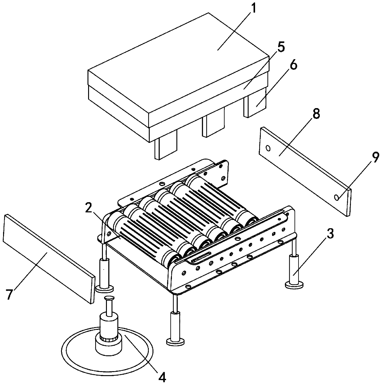
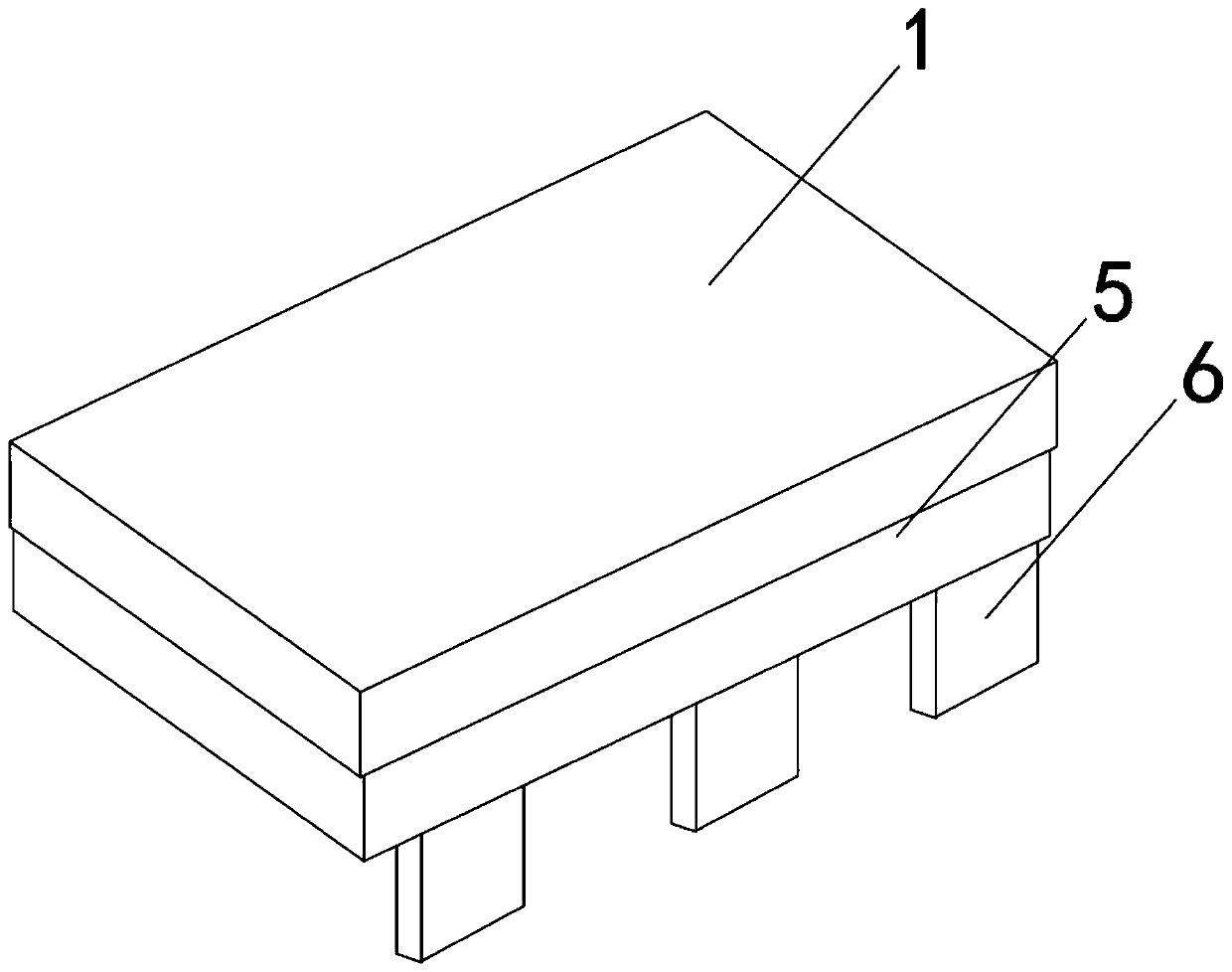
[0050] see Figure 1-16 As shown, a special photo-oxygen catalytic device for waste gas treatment includes an upper cover 1, a catalytic box 2, four legs 3 and a turntable 4, a catalytic box 2 is arranged under the upper cover 1, and the four legs 3 are vertically arranged on the catalytic There are four corners at the bottom of the box 2, and a turntable 4 is arranged in the middle of the bottom of the catalytic box 2;

[0051] The top cover 1 is a hollow structure, and several purple lamp panels 10 are arranged at equal ...


PUM


Abstract

The invention discloses a special photooxygen catalytic device for waste gas treatment, the special photooxygen catalytic device comprises an upper mounting cover, a catalytic box, four supporting legs and a rotary table; the catalytic box is arranged below the upper mounting cover, and the four supporting legs are vertically arranged at the four corners of the bottom of the catalytic box respectively, the rotary table is arranged in the middle of the bottom of the catalytic box, and the upper mounting cover is of a hollow structure. The special photooxygen catalytic device has the beneficialeffects that a plurality of rotary plates are used for respectively introducing waste gas, so that the waste gas can be uniformly dispersed in the catalytic box through air outlet holes, motors II ona plurality of ultraviolet lamp panels are matched to drive a plurality of lamp tubes on the two sides to swing up and down in a reciprocating manner, motors I drive the plurality of lamp tubes to rotate continuously, the angle and the position range of the waste gas being irradiated by the lamp tubes are expanded, and the ultraviolet lamp panels are enabled to irradiate ultraviolet rays to the waste gas more comprehensively, so that the waste gas is oxidized and deodorized and sterilized more comprehensively and thoroughly; the device is convenient to operate, firm and durable, has good social benefits and is suitable for popularization and application.

Description

technical field [0001] The invention relates to a photo-oxygen catalytic device, specifically a photo-oxygen catalytic device for waste gas treatment, and belongs to the application technical field of photo-oxygen catalytic devices for waste gas treatment. Background technique [0002] The photo-oxygen catalytic device uses a purple light tube to irradiate UV ultraviolet light beams to irradiate malodorous gases in exhaust gas, change the molecular chains of organic or inorganic high-molecular odor compounds in odorous gases, and degrade them into low-molecular compounds under the irradiation of high-energy ultraviolet light beams, such as CO2, H2O, etc., the photo-oxygen catalytic device uses UV ultraviolet light to decompose oxygen molecules in the air to generate free oxygen, that is, active oxygen. Because the positive and negative electrons carried by free oxygen are unbalanced, they need to combine with oxygen molecules to generate ozone. Ozone and The malodorous gas i...

Claims


Application Information

Patent Timeline
Patent Type & Authority Applications(China)
IPC IPC(8): B01D53/74B01D53/86
Inventor 耿良飞
Owner 苏州弘维环境科技有限公司
Why Eureka
Try Eureka