Motion planning model for automobile welding robot

A welding robot, robot movement technology, applied in the direction of manipulators, program control manipulators, manufacturing tools, etc.

Active Publication Date: 2019-05-28
浙江鲁邦智能装备科技有限公司
View PDF8 Cites 0 Cited by
  • Summary
  • Abstract
  • Description
  • Claims
  • Application Information

AI Technical Summary

Problems solved by technology

The present invention uses an optimization method to solve the motion optimization problem of the automobile welding robot, establishes a mathematical model according to actual requirements, and optimizes the performance of the automobile welding robot under the condition of ensuring the stability of the welding automobile welding robot

Method used


Image

  • Motion planning model for automobile welding robot
  • Motion planning model for automobile welding robot
  • Motion planning model for automobile welding robot

Examples


Embodiment Construction

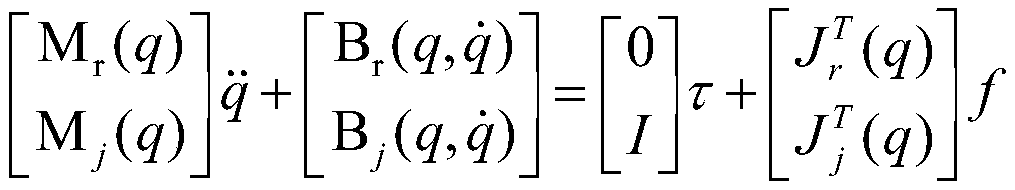
[0039] In the motion planning model of the present invention, the automobile welding robot is defined as a tree-shaped automobile welding robot assembled by joints with some rigid bodies, that is, the main body is a node and the joint is an edge; the motion planning model includes a displacement control variable q (t), which is called configuration, the parameter vector of the joint is the control variable of the motion planning model, q(t) is abbreviated as q, and the admissible function q needs to satisfy the following physical meaning of the motion equation EoM :

[0040]

[0041] = where the subscript r represents the automobile welding robot, the subscript j represents the joint, and M r Indicates the inertia of the automobile welding robot, B r Indicates the influence factor brought by the gravity and speed of the automobile welding robot, M j Indicates the inertia of the joint, B j Indicates the influence factor brought by the gravity and speed of the joint, τ is ...


PUM


Abstract

The invention relates to a motion planning model of an automobile welding robot; the automobile welding robot is defined as a tree-shaped automobile welding robot formed by assembling a plurality of rigid main bodies and joints, namely, the main bodies are nodes and joints are edges; the parameter vector of the joints is the control variable of the motion planning model, the allowable function meets the motion equation EOM, and the allowable function is used as a constraint to form the motion planning model; the solving method of the motion planning model is a non-smooth conversion method of awelding robot node space. According to the invention, the motion planning model problem is ascribed to a non-smooth optimization problem, and the non-smooth optimization problem can be solved by using a parallel computing technique. In the invention, a motion planning mathematical model can be established according to actual requirements, and the model optimizes the performance of the automobilewelding robot under the condition of ensuring the stability of the automobile welding robot.

Description

technical field [0001] The invention belongs to the technical field of automation control, and in particular relates to a motion planning model of an automobile welding robot. Background technique [0002] Robot technology is an intelligent technology that converts digital data into physical actions after processing. The core of any robot system research and development is the trajectory. The scientific solution to calculate the trajectory of the robot to achieve the desired purpose or complete the desired task is the robot movement. planning model. Because of the diversity and uncertainty of the models and environments used for motion calculation, the motion planning model should be realized through closed-loop control. In the automotive welding robot, because the task is determined in advance, it is required to achieve the maximum motion speed and robustness performance under the constraints of the motion performance or under the constraints of the joint range, speed, and...

Claims


Application Information

Patent Timeline
IPC IPC(8): B25J9/16B25J11/00
Inventor 庞丽萍王金鹤肖泽昊孟凡云
Owner 浙江鲁邦智能装备科技有限公司
Why Eureka
Try Eureka